Engine that uses steam to perform mechanical work
 A model of a beam engine featuring James Watt's parallel linkage for double action
[a]
A model of a beam engine featuring James Watt's parallel linkage for double action
[a]
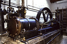 A
mill engine
from
Stott Park Bobbin Mill
, Cumbria, England
A
mill engine
from
Stott Park Bobbin Mill
, Cumbria, England
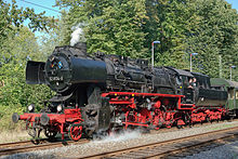 A
steam locomotive
from
East Germany
. This
class
of engine was built in 1942?1950 and operated until 1988.
A
steam locomotive
from
East Germany
. This
class
of engine was built in 1942?1950 and operated until 1988.
 A steam ploughing engine by
Kemna
A steam ploughing engine by
Kemna
A
steam engine
is a
heat engine
that performs
mechanical work
using
steam
as its
working fluid
. The steam engine uses the force produced by steam pressure to push a
piston
back and forth inside a
cylinder
. This pushing force can be transformed, by a
connecting rod
and
crank
, into
rotational
force for work. The term "steam engine" is most commonly applied to
reciprocating engines
as just described, although some authorities have also referred to the
steam turbine
and devices such as Hero's
aeolipile
as "steam engines". The essential feature of steam engines is that they are
external combustion engines
,
[1]
where the working fluid is separated from the combustion products. The ideal
thermodynamic
cycle used to analyze this process is called the
Rankine cycle
. In general usage, the term
steam engine
can refer to either complete steam plants (including
boilers
etc.), such as railway
steam locomotives
and
portable engines
, or may refer to the
piston
or turbine machinery alone, as in the
beam engine
and
stationary steam engine
.
As noted, steam-driven devices such as the aeolipile were known in the first century AD, and there were a few other uses recorded in the 16th century. In 1606
Jeronimo de Ayanz y Beaumont
patented his invention of the first steam-powered water pump for draining mines.
[2]
Thomas Savery
is considered the inventor of the first commercially used steam powered device, a steam pump that used steam pressure operating directly on the water. The first commercially successful engine that could transmit continuous power to a machine was developed in 1712 by
Thomas Newcomen
.
James Watt
made a critical improvement in 1764, by removing spent steam to a separate vessel for condensation, greatly improving the amount of work obtained per unit of fuel consumed. By the 19th century, stationary steam engines powered the factories of the
Industrial Revolution
. Steam engines replaced
sails for ships
on
paddle steamers
, and steam locomotives operated on the railways.
Reciprocating piston type steam engines were the dominant source of power until the early 20th century. The efficiency of stationary steam engine increased dramatically until about 1922.
[3]
The highest Rankine Cycle Efficiency of 91% and combined thermal efficiency of 31% was demonstrated and published in 1921 and 1928.
[4]
Advances in the design of
electric motors
and
internal combustion engines
resulted in the gradual replacement of steam engines in commercial usage. Steam turbines replaced reciprocating engines in power generation, due to lower cost, higher operating speed, and higher efficiency.
[5]
Note that small scale steam turbines are much less efficient than large ones.
[6]
As of 2023
[update]
, large reciprocating piston steam engines are still being manufactured in Germany.
[7]
History
[
edit
]
Early experiments
[
edit
]
As noted, one recorded rudimentary steam-powered engine was the
aeolipile
described by
Hero of Alexandria
, a Greek mathematician and engineer in
Roman Egypt
in the first century AD.
[8]
In the following centuries, the few steam-powered engines known were, like the aeolipile,
[9]
essentially experimental devices used by inventors to demonstrate the properties of steam.
A rudimentary
steam turbine
device was described by
Taqi al-Din
[10]
in
Ottoman Egypt
in 1551 and by
Giovanni Branca
[11]
in Italy in 1629.
The Spanish inventor
Jeronimo de Ayanz y Beaumont
received patents in 1606 for 50 steam-powered inventions, including a water pump for draining inundated mines.
[13]
Frenchman
Denis Papin
did some useful work on the
steam digester
in 1679, and first used a piston to raise weights in 1690.
Pumping engines
[
edit
]
The first commercial steam-powered device was a water pump, developed in 1698 by
Thomas Savery
.
[15]
It used condensing steam to create a vacuum which raised water from below and then used steam pressure to raise it higher. Small engines were effective though larger models were problematic. They had a very limited lift height and were prone to
boiler explosions
. Savery's engine was used in mines,
pumping stations
and supplying water to
water wheels
powering textile machinery.
[16]
Savery's engine was of low cost.
Bento de Moura Portugal
introduced an improvement of Savery's construction "to render it capable of working itself", as described by
John Smeaton
in the Philosophical Transactions published in 1751.
[17]
It continued to be manufactured until the late 18th century.
[18]
At least one engine was still known to be operating in 1820.
[19]
Piston steam engines
[
edit
]
 Jacob Leupold
's steam engine, 1720
Jacob Leupold
's steam engine, 1720
The first commercially successful engine that could transmit continuous power to a machine was the
atmospheric engine
, invented by
Thomas Newcomen
around 1712.
[b]
It improved on Savery's steam pump, using a piston as proposed by Papin. Newcomen's engine was relatively inefficient, and mostly used for pumping water. It worked by creating a partial vacuum by condensing steam under a piston within a cylinder. It was employed for draining mine workings at depths originally impractical using traditional means, and for providing reusable water for driving waterwheels at factories sited away from a suitable "head". Water that passed over the wheel was pumped up into a storage reservoir above the wheel.
[23]
In 1780 James Pickard patented the use of a flywheel and crankshaft to provide rotative motion from an improved Newcomen engine.
In 1720,
Jacob Leupold
described a two-cylinder high-pressure steam engine.
[25]
The invention was published in his major work "Theatri Machinarum Hydraulicarum".
[26]
The engine used two heavy pistons to provide motion to a water pump. Each piston was raised by the steam pressure and returned to its original position by gravity. The two pistons shared a common four-way
rotary valve
connected directly to a steam boiler.
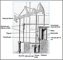 Early
Watt
pumping engine
Early
Watt
pumping engine
The next major step occurred when
James Watt
developed (1763?1775)
an improved version
of Newcomen's engine, with a
separate condenser
.
Boulton and Watt
's early engines used half as much coal as
John Smeaton
's improved version of Newcomen's.
[27]
Newcomen's and Watt's early engines were "atmospheric". They were powered by air pressure pushing a piston into the partial
vacuum
generated by
condensing
steam, instead of the
pressure
of expanding steam. The engine
cylinders
had to be large because the only usable force acting on them was
atmospheric pressure
.
[28]
Watt developed his engine further, modifying it to provide a rotary motion suitable for driving machinery. This enabled factories to be sited away from rivers, and accelerated the pace of the Industrial Revolution.
[28]
[29]
High-pressure engines
[
edit
]
The meaning of high pressure, together with an actual value above ambient, depends on the era in which the term was used. For early use of the term Van Reimsdijk
[30]
refers to steam being at a sufficiently high pressure that it could be exhausted to atmosphere without reliance on a vacuum to enable it to perform useful work.
Ewing 1894
, p. 22 states that Watt's condensing engines were known, at the time, as low pressure compared to high pressure, non-condensing engines of the same period.
Watt's patent prevented others from making high pressure and compound engines. Shortly after Watt's patent expired in 1800,
Richard Trevithick
and, separately,
Oliver Evans
in 1801
[29]
[31]
introduced engines using high-pressure steam; Trevithick obtained his high-pressure engine patent in 1802,
[32]
and Evans had made several working models before then.
[33]
These were much more powerful for a given cylinder size than previous engines and could be made small enough for transport applications. Thereafter, technological developments and improvements in manufacturing techniques (partly brought about by the adoption of the steam engine as a power source) resulted in the design of more efficient engines that could be smaller, faster, or more powerful, depending on the intended application.
The
Cornish engine
was developed by Trevithick and others in the 1810s.
It was a compound cycle engine that used high-pressure steam expansively, then condensed the low-pressure steam, making it relatively efficient. The Cornish engine had irregular motion and torque through the cycle, limiting it mainly to pumping. Cornish engines were used in mines and for water supply until the late 19th century.
Horizontal stationary engine
[
edit
]
Early builders of stationary steam engines considered that horizontal cylinders would be subject to excessive wear. Their engines were therefore arranged with the piston axis in vertical position. In time the horizontal arrangement became more popular, allowing compact, but powerful engines to be fitted in smaller spaces.
The acme of the horizontal engine was the
Corliss steam engine
, patented in 1849, which was a four-valve counter flow engine with separate steam admission and exhaust valves and automatic variable steam cutoff. When Corliss was given the
Rumford Medal
, the committee said that "no one invention since Watt's time has so enhanced the efficiency of the steam engine".
[36]
In addition to using 30% less steam, it provided more uniform speed due to variable steam cut off, making it well suited to manufacturing, especially cotton spinning.
[29]
Road vehicles
[
edit
]
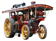 Steam powered road-locomotive from England
The first experimental road-going steam-powered vehicles were built in the late 18th century, but it was not until after
Richard Trevithick
had developed the use of high-pressure steam, around 1800, that mobile steam engines became a practical proposition. The first half of the 19th century saw great progress in steam vehicle design, and by the 1850s it was becoming viable to produce them on a commercial basis. This progress was dampened by legislation which limited or prohibited the use of steam-powered vehicles on roads. Improvements in vehicle technology continued from the 1860s to the 1920s. Steam road vehicles were used for many applications. In the 20th century, the rapid development of
internal combustion engine
technology led to the demise of the steam engine as a source of propulsion of vehicles on a commercial basis, with relatively few remaining in use beyond the
Second World War
. Many of these vehicles were acquired by enthusiasts for preservation, and numerous examples are still in existence. In the 1960s, the air pollution problems in California gave rise to a brief period of interest in developing and studying steam-powered vehicles as a possible means of reducing the pollution. Apart from interest by steam enthusiasts, the occasional replica vehicle, and experimental technology, no steam vehicles are in production at present.
Marine engines
[
edit
]
 A triple-expansion
marine steam engine
on the 1907 oceangoing tug
Hercules
A triple-expansion
marine steam engine
on the 1907 oceangoing tug
Hercules
Near the end of the 19th century, compound engines came into widespread use.
Compound engines
exhausted steam into successively larger cylinders to accommodate the higher volumes at reduced pressures, giving improved efficiency. These stages were called expansions, with double- and triple-expansion engines being common, especially in shipping where efficiency was important to reduce the weight of coal carried.
Steam engines remained the dominant source of power until the early 20th century, when advances in the design of the
steam turbine
,
electric motors
and
internal combustion engines
gradually resulted in the replacement of reciprocating (piston) steam engines, with merchant shipping relying increasingly upon
diesel engines
, and warships on the steam turbine.
[5]
Steam locomotives
[
edit
]
As the development of steam engines progressed through the 18th century, various attempts were made to apply them to road and railway use.
In 1784,
William Murdoch
, a
Scottish
inventor, built a model steam road locomotive.
[38]
An early working model of a steam rail locomotive was designed and constructed by steamboat pioneer
John Fitch
in the United States probably during the 1780s or 1790s.
[39]
His steam locomotive used interior bladed wheels
[
clarification needed
]
guided by rails or tracks.
 Union Pacific 844
, an "
FEF-3
"
4-8-4
"Northern" type steam locomotive
Union Pacific 844
, an "
FEF-3
"
4-8-4
"Northern" type steam locomotive
The first full-scale working railway steam locomotive was built by
Richard Trevithick
in the
United Kingdom
and, on 21 February 1804, the world's first railway journey took place as Trevithick's unnamed steam locomotive hauled a train along the
tramway
from the
Pen-y-darren
ironworks, near
Merthyr Tydfil
to
Abercynon
in south
Wales
.
[40]
[41]
The design incorporated a number of important innovations that included using high-pressure steam which reduced the weight of the engine and increased its efficiency. Trevithick visited the Newcastle area later in 1804 and the
colliery railways
in north-east England became the leading centre for experimentation and development of steam locomotives.
[42]
Trevithick continued his own experiments using a trio of locomotives, concluding with the
Catch Me Who Can
in 1808. Only four years later, the successful twin-cylinder locomotive
Salamanca
by
Matthew Murray
was used by the
edge railed
rack and pinion
Middleton Railway
.
[43]
In 1825
George Stephenson
built the
Locomotion
for the
Stockton and Darlington Railway
. This was the first public steam railway in the world and then in 1829, he built
The Rocket
which was entered in and won the
Rainhill Trials
.
[44]
The
Liverpool and Manchester Railway
opened in 1830 making exclusive use of steam power for both passenger and freight trains.
Steam locomotives continued to be manufactured until the late twentieth century in places such as
China
and the former
East Germany
(where the
DR Class 52.80
was produced).
[45]
Steam turbines
[
edit
]
The final major evolution of the steam engine design was the use of steam
turbines
starting in the late part of the 19th century. Steam turbines are generally more efficient than reciprocating piston type steam engines (for outputs above several hundred horsepower), have fewer moving parts, and provide rotary power directly instead of through a
connecting rod
system or similar means.
[46]
Steam turbines virtually replaced reciprocating engines in electricity generating stations early in the 20th century, where their efficiency, higher speed appropriate to generator service, and smooth rotation were advantages. Today most
electric power
is provided by steam turbines. In the United States, 90% of the electric power is produced in this way using a variety of heat sources.
[5]
Steam turbines were extensively applied for propulsion of large ships throughout most of the 20th century.
Present development
[
edit
]
Although the reciprocating steam engine is no longer in widespread commercial use, various companies are exploring or exploiting the potential of the engine as an alternative to internal combustion engines.
Components and accessories of steam engines
[
edit
]
There are two fundamental components of a steam plant: the
boiler
or
steam generator
, and the "motor unit", referred to itself as a "steam engine".
Stationary steam engines
in fixed buildings may have the boiler and engine in separate buildings some distance apart. For portable or mobile use, such as
steam locomotives
, the two are mounted together.
[47]
[48]
The widely used reciprocating engine typically consisted of a cast-iron cylinder, piston, connecting rod and beam or a crank and flywheel, and miscellaneous linkages. Steam was alternately supplied and exhausted by one or more valves. Speed control was either automatic, using a governor, or by a manual valve. The cylinder casting contained steam supply and exhaust ports.
Engines equipped with a condenser are a separate type than those that exhaust to the atmosphere.
Other components are often present; pumps (such as an
injector
) to supply water to the boiler during operation, condensers to recirculate the water and recover the
latent heat
of vaporisation, and
superheaters
to raise the temperature of the steam above its saturated vapour point, and various mechanisms to increase the draft for fireboxes. When coal is used, a chain or screw stoking mechanism and its drive engine or motor may be included to move the fuel from a supply bin (bunker) to the firebox.
[49]
Heat source
[
edit
]
The heat required for boiling the water and raising the temperature of the steam can be derived from various sources, most commonly from burning combustible materials with an appropriate supply of air in a closed space (e.g.,
combustion chamber
,
firebox
, furnace). In the case of
model or toy steam engines
and a few full scale cases, the heat source can be an
electric heating element
.
Boilers
[
edit
]
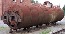 An industrial boiler used for a
stationary steam engine
An industrial boiler used for a
stationary steam engine
Boilers are
pressure vessels
that contain water to be boiled, and features that
transfer the heat to the water
as effectively as possible.
The two most common types are:
- Water-tube boiler
- Water is passed through tubes surrounded by hot gas.
- Fire-tube boiler
- Hot gas is passed through tubes immersed in water, the same water also circulates in a water jacket surrounding the firebox and, in high-output locomotive boilers, also passes through tubes in the firebox itself (thermic syphons and security circulators).
Fire-tube boilers were the main type used for early high-pressure steam (typical steam locomotive practice), but they were to a large extent displaced by more economical water tube boilers in the late 19th century for marine propulsion and large stationary applications.
Many boilers raise the temperature of the steam after it has left that part of the boiler where it is in contact with the water. Known as
superheating
it turns '
wet steam
' into '
superheated steam
'. It avoids the steam condensing in the engine cylinders, and gives a significantly higher
efficiency
.
[51]
Motor units
[
edit
]
In a steam engine, a piston or steam turbine or any other similar device for doing mechanical work takes a supply of steam at high pressure and temperature and gives out a supply of steam at lower pressure and temperature, using as much of the difference in steam energy as possible to do mechanical work.
These "motor units" are often called 'steam engines' in their own right. Engines using compressed air or other gases differ from steam engines only in details that depend on the nature of the gas although
compressed air
has been used in steam engines without change.
[51]
Cold sink
[
edit
]
As with all heat engines, the majority of
primary energy
must be emitted as
waste heat
at relatively low temperature.
[52]
The simplest cold sink is to vent the steam to the environment. This is often used on
steam locomotives
to avoid the weight and bulk of condensers. Some of the released steam is vented up the chimney so as to increase the draw on the fire, which greatly increases engine power, but reduces efficiency.
Sometimes the waste heat from the engine is useful itself, and in those cases, very high overall efficiency can be obtained.
Steam engines in stationary power plants use
surface condensers
as a cold sink. The condensers are cooled by water flow from oceans, rivers, lakes, and often by
cooling towers
which evaporate water to provide cooling energy removal. The resulting condensed hot water (
condensate
), is then pumped back up to pressure and sent back to the boiler. A dry-type cooling tower is similar to an automobile radiator and is used in locations where water is costly. Waste heat can also be ejected by evaporative (wet) cooling towers, which use a secondary external water circuit that evaporates some of flow to the air.
River boats initially used a
jet condenser
in which cold water from the river is injected into the exhaust steam from the engine. Cooling water and condensate mix. While this was also applied for sea-going vessels, generally after only a few days of operation the boiler would become coated with deposited salt, reducing performance and increasing the risk of a boiler explosion. Starting about 1834, the use of surface condensers on ships eliminated fouling of the boilers, and improved engine efficiency.
[53]
Evaporated water cannot be used for subsequent purposes (other than rain somewhere), whereas river water can be re-used. In all cases, the steam plant boiler feed water, which must be kept pure, is kept separate from the cooling water or air.
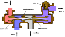 An
injector
uses a jet of steam to force water into the boiler. Injectors are inefficient but simple enough to be suitable for use on locomotives.
An
injector
uses a jet of steam to force water into the boiler. Injectors are inefficient but simple enough to be suitable for use on locomotives.
Water pump
[
edit
]
Most steam boilers have a means to supply water whilst at pressure, so that they may be run continuously. Utility and industrial boilers commonly use multi-stage
centrifugal pumps
; however, other types are used. Another means of supplying lower-pressure boiler feed water is an
injector
, which uses a steam jet usually supplied from the boiler. Injectors became popular in the 1850s but are no longer widely used, except in applications such as steam locomotives.
It is the pressurization of the water that circulates through the steam boiler that allows the water to be raised to temperatures well above 100 °C (212 °F) boiling point of water at one atmospheric pressure, and by that means to increase the efficiency of the steam cycle.
Monitoring and control
[
edit
]
 Richard's indicator instrument of 1875. See: Indicator diagram (below)
For safety reasons, nearly all steam engines are equipped with mechanisms to monitor the boiler, such as a
pressure gauge
and a
sight glass
to monitor the water level.
Many engines, stationary and mobile, are also fitted with a
governor
to regulate the speed of the engine without the need for human interference.
The most useful instrument for analyzing the performance of steam engines is the steam engine indicator. Early versions were in use by 1851,
but the most successful indicator was developed for the high speed engine inventor and manufacturer Charles Porter by Charles Richard and exhibited at London Exhibition in 1862.
[29]
The steam engine indicator traces on paper the pressure in the cylinder throughout the cycle, which can be used to spot various problems and calculate developed horsepower.
[56]
It was routinely used by engineers, mechanics and insurance inspectors. The engine indicator can also be used on internal combustion engines. See image of indicator diagram below (in
Types of motor units
section).
Governor
[
edit
]
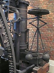 Centrifugal governor
in the
Boulton & Watt engine
1788
Lap Engine
.
Centrifugal governor
in the
Boulton & Watt engine
1788
Lap Engine
.
The
centrifugal governor
was adopted by James Watt for use on a steam engine in 1788 after Watt's partner Boulton saw one on the equipment of a flour mill
Boulton & Watt
were building.
[57]
The governor could not actually hold a set speed, because it would assume a new constant speed in response to load changes. The governor was able to handle smaller variations such as those caused by fluctuating heat load to the boiler. Also, there was a tendency for oscillation whenever there was a speed change. As a consequence, engines equipped only with this governor were not suitable for operations requiring constant speed, such as cotton spinning.
[58]
The governor was improved over time and coupled with variable steam cut off, good speed control in response to changes in load was attainable near the end of the 19th century.
Engine configuration
[
edit
]
Simple engine
[
edit
]
In a simple engine, or "single expansion engine" the charge of steam passes through the entire expansion process in an individual cylinder, although a simple engine may have one or more individual cylinders.
[59]
It is then exhausted directly into the atmosphere or into a condenser. As steam expands in passing through a high-pressure engine, its temperature drops because no heat is being added to the system; this is known as
adiabatic expansion
and results in steam entering the cylinder at high temperature and leaving at lower temperature. This causes a cycle of heating and cooling of the cylinder with every stroke, which is a source of inefficiency.
The dominant efficiency loss in reciprocating steam engines is cylinder condensation and re-evaporation. The steam cylinder and adjacent metal parts/ports operate at a temperature about halfway between the steam admission saturation temperature and the saturation temperature corresponding to the exhaust pressure. As high-pressure steam is admitted into the working cylinder, much of the high-temperature steam is condensed as water droplets onto the metal surfaces, significantly reducing the steam available for expansive work. When the expanding steam reaches low pressure (especially during the exhaust stroke), the previously deposited water droplets that had just been formed within the cylinder/ports now boil away (re-evaporation) and this steam does no further work in the cylinder.
[
citation needed
]
There are practical limits on the expansion ratio of a steam engine cylinder, as increasing cylinder surface area tends to exacerbate the cylinder condensation and re-evaporation issues. This negates the theoretical advantages associated with a high ratio of expansion in an individual cylinder.
[61]
Compound engines
[
edit
]
A method to lessen the magnitude of energy loss to a very long cylinder was invented in 1804 by British engineer
Arthur Woolf
, who patented his
Woolf high-pressure
compound engine
in 1805. In the compound engine, high-pressure steam from the boiler expands in a
high-pressure (HP) cylinder
and then enters one or more subsequent
lower-pressure (LP) cylinders
. The complete expansion of the steam now occurs across multiple cylinders, with the overall temperature drop within each cylinder reduced considerably. By expanding the steam in steps with smaller temperature range (within each cylinder) the condensation and re-evaporation efficiency issue (described above) is reduced. This reduces the magnitude of cylinder heating and cooling, increasing the efficiency of the engine. By staging the expansion in multiple cylinders, variations of torque can be reduced.
To derive equal work from lower-pressure cylinder requires a larger cylinder volume as this steam occupies a greater volume. Therefore, the bore, and in rare cases the stroke, are increased in low-pressure cylinders, resulting in larger cylinders.
Double-expansion (usually known as
compound
) engines expanded the steam in two stages. The pairs may be duplicated or the work of the large low-pressure cylinder can be split with one high-pressure cylinder exhausting into one or the other, giving a three-cylinder layout where cylinder and piston diameter are about the same, making the reciprocating masses easier to balance.
Two-cylinder compounds can be arranged as:
- Cross compounds
: The cylinders are side by side.
- Tandem compounds
: The cylinders are end to end, driving a common
connecting rod
- Angle compounds
: The cylinders are arranged in a V (usually at a 90° angle) and drive a common crank.
With two-cylinder compounds used in railway work, the pistons are connected to the cranks as with a two-cylinder simple at 90° out of phase with each other (
quartered
). When the double-expansion group is duplicated, producing a four-cylinder compound, the individual pistons within the group are usually balanced at 180°, the groups being set at 90° to each other. In one case (the first type of
Vauclain compound
), the pistons worked in the same phase driving a common crosshead and crank, again set at 90° as for a two-cylinder engine. With the three-cylinder compound arrangement, the LP cranks were either set at 90° with the HP one at 135° to the other two, or in some cases, all three cranks were set at 120°.
[
citation needed
]
The adoption of compounding was common for industrial units, for road engines and almost universal for marine engines after 1880; it was not universally popular in railway locomotives where it was often perceived as complicated. This is partly due to the harsh railway operating environment and limited space afforded by the
loading gauge
(particularly in Britain, where compounding was never common and not employed after 1930). However, although never in the majority, it was popular in many other countries.
[62]
Multiple-expansion engines
[
edit
]
 An animation of a simplified triple-expansion engine. High-pressure steam (red) enters from the boiler and passes through the engine, exhausting as low-pressure steam (blue), usually to a condenser.
It is a logical extension of the compound engine (described above) to split the expansion into yet more stages to increase efficiency. The result is the
multiple-expansion engine
. Such engines use either three or four expansion stages and are known as
triple-
and
quadruple-expansion engines
respectively. These engines use a series of cylinders of progressively increasing diameter. These cylinders are designed to divide the work into equal shares for each expansion stage. As with the double-expansion engine, if space is at a premium, then two smaller cylinders may be used for the low-pressure stage. Multiple-expansion engines typically had the cylinders arranged inline, but various other formations were used. In the late 19th century, the
Yarrow-Schlick-Tweedy balancing "system"
was used on some
marine triple-expansion engines
. Y-S-T engines divided the low-pressure expansion stages between two cylinders, one at each end of the engine. This allowed the crankshaft to be better balanced, resulting in a smoother, faster-responding engine which ran with less vibration. This made the four-cylinder triple-expansion engine popular with large passenger liners (such as the
Olympic
class
), but this was ultimately replaced by the virtually vibration-free
turbine engine
.
[
citation needed
]
It is noted, however, that triple-expansion reciprocating steam engines were used to drive the World War II
Liberty ships
, by far the largest number of identical ships ever built. Over 2700 ships were built, in the United States, from a British original design.
[
citation needed
]
The image in this section shows an animation of a triple-expansion engine. The steam travels through the engine from left to right. The valve chest for each of the cylinders is to the left of the corresponding cylinder.
[
citation needed
]
Land-based steam engines could exhaust their steam to atmosphere, as feed water was usually readily available. Prior to and during
World War I
, the expansion engine dominated marine applications, where high vessel speed was not essential. It was, however, superseded by the British invention
steam turbine
where speed was required, for instance in warships, such as the
dreadnought battleships
, and
ocean liners
.
HMS
Dreadnought
of 1905 was the first major warship to replace the proven technology of the reciprocating engine with the then-novel steam turbine.
[63]
Types of motor units
[
edit
]
Reciprocating piston
[
edit
]
 Double acting
stationary engine. This was the common mill engine of the mid 19th century. Note the
slide valve
with concave, almost D-shaped, underside.
Double acting
stationary engine. This was the common mill engine of the mid 19th century. Note the
slide valve
with concave, almost D-shaped, underside.
 Schematic
Indicator diagram
showing the four events in a double piston stroke. See: Monitoring and control (above)
Schematic
Indicator diagram
showing the four events in a double piston stroke. See: Monitoring and control (above)
In most reciprocating piston engines, the steam reverses its direction of flow at each
stroke
(counterflow), entering and exhausting from the same end of the cylinder. The complete engine cycle occupies one rotation of the crank and two piston strokes; the cycle also comprises four
events
? admission, expansion, exhaust, compression. These events are controlled by valves often working inside a
steam chest
adjacent to the cylinder; the valves distribute the steam by opening and closing steam
ports
communicating with the cylinder end(s) and are driven by
valve gear
, of which there are many types.
[64]
The simplest valve gears give events of fixed length during the engine cycle and often make the engine rotate in only one direction. Many however have a reversing
mechanism
which additionally can provide means for saving steam as speed and momentum are gained by gradually "shortening the
cutoff
" or rather, shortening the admission event; this in turn proportionately lengthens the expansion period. However, as one and the same valve usually controls both steam flows, a short cutoff at admission adversely affects the exhaust and compression periods which should ideally always be kept fairly constant; if the exhaust event is too brief, the totality of the exhaust steam cannot evacuate the cylinder, choking it and giving excessive compression (
"kick back"
).
[65]
In the 1840s and 1850s, there were attempts to overcome this problem by means of various patent valve gears with a separate, variable cutoff
expansion valve
riding on the back of the main slide valve; the latter usually had fixed or limited cutoff. The combined setup gave a fair approximation of the ideal events, at the expense of increased friction and wear, and the mechanism tended to be complicated. The usual compromise solution has been to provide
lap
by lengthening rubbing surfaces of the valve in such a way as to overlap the port on the admission side, with the effect that the exhaust side remains open for a longer period after cut-off on the admission side has occurred. This expedient has since been generally considered satisfactory for most purposes and makes possible the use of the simpler
Stephenson
,
Joy
and
Walschaerts
motions.
Corliss
, and later,
poppet valve
gears had separate admission and exhaust valves driven by
trip mechanisms
or
cams
profiled so as to give ideal events; most of these gears never succeeded outside of the stationary marketplace due to various other issues including leakage and more delicate mechanisms.
[62]
Compression
[
edit
]
Before the exhaust phase is quite complete, the exhaust side of the valve closes, shutting a portion of the exhaust steam inside the cylinder. This determines the compression phase where a cushion of steam is formed against which the piston does work whilst its velocity is rapidly decreasing; it moreover obviates the pressure and temperature shock, which would otherwise be caused by the sudden admission of the high-pressure steam at the beginning of the following cycle.
[
citation needed
]
Lead in the valve timing
[
edit
]
The above effects are further enhanced by providing
lead
: as was later discovered with the
internal combustion engine
, it has been found advantageous since the late 1830s to advance the admission phase, giving the valve
lead
so that admission occurs a little before the end of the exhaust stroke in order to fill the
clearance volume
comprising the ports and the cylinder ends (not part of the piston-swept volume) before the steam begins to exert effort on the piston.
[67]
Uniflow (or unaflow) engine
[
edit
]
 Animation of a
uniflow steam engine
.
Animation of a
uniflow steam engine
.
The
poppet valves
are controlled by the rotating
camshaft
at the top. High-pressure steam enters, red, and exhausts, yellow.
Uniflow engines attempt to remedy the difficulties arising from the usual counterflow cycle where, during each stroke, the port and the cylinder walls will be cooled by the passing exhaust steam, whilst the hotter incoming admission steam will waste some of its energy in restoring the working temperature. The aim of the uniflow is to remedy this defect and improve efficiency by providing an additional port uncovered by the piston at the end of each stroke making the steam flow only in one direction. By this means, the simple-expansion uniflow engine gives efficiency equivalent to that of classic compound systems with the added advantage of superior part-load performance, and comparable efficiency to turbines for smaller engines below one thousand horsepower. However, the thermal expansion gradient uniflow engines produce along the cylinder wall gives practical difficulties.
[
citation needed
]
.
Turbine engines
[
edit
]
 A rotor of a modern
steam turbine
, used in a
power plant
A rotor of a modern
steam turbine
, used in a
power plant
A steam turbine consists of one or more
rotors
(rotating discs) mounted on a drive shaft, alternating with a series of
stators
(static discs) fixed to the turbine casing. The rotors have a propeller-like arrangement of blades at the outer edge. Steam acts upon these blades, producing rotary motion. The stator consists of a similar, but fixed, series of blades that serve to redirect the steam flow onto the next rotor stage. A steam turbine often exhausts into a
surface condenser
that provides a vacuum. The stages of a steam turbine are typically arranged to extract the maximum potential work from a specific velocity and pressure of steam, giving rise to a series of variably sized high- and low-pressure stages. Turbines are only efficient if they rotate at relatively high speed, therefore they are usually connected to reduction gearing to drive lower speed applications, such as a ship's propeller. In the vast majority of large electric generating stations, turbines are directly connected to generators with no reduction gearing. Typical speeds are 3600 revolutions per minute (RPM) in the United States with 60 Hertz power, and 3000 RPM in Europe and other countries with 50 Hertz electric power systems. In nuclear power applications, the turbines typically run at half these speeds, 1800 RPM and 1500 RPM. A turbine rotor is also only capable of providing power when rotating in one direction. Therefore, a reversing stage or gearbox is usually required where power is required in the opposite direction.
[
citation needed
]
Steam turbines provide direct rotational force and therefore do not require a linkage mechanism to convert reciprocating to rotary motion. Thus, they produce smoother rotational forces on the output shaft. This contributes to a lower maintenance requirement and less wear on the machinery they power than a comparable reciprocating engine.
[
citation needed
]
 Turbinia
? the first
steam turbine
-powered ship
Turbinia
? the first
steam turbine
-powered ship
The main use for steam turbines is in
electricity generation
(in the 1990s about 90% of the world's electric production was by use of steam turbines)
[5]
however the recent widespread application of large gas turbine units and typical combined cycle power plants has resulted in reduction of this percentage to the 80% regime for steam turbines. In electricity production, the high speed of turbine rotation matches well with the speed of modern electric generators, which are typically direct connected to their driving turbines. In marine service, (pioneered on the
Turbinia
), steam turbines with reduction gearing (although the Turbinia has direct turbines to propellers with no reduction gearbox) dominated large ship propulsion throughout the late 20th century, being more efficient (and requiring far less maintenance) than reciprocating steam engines. In recent decades, reciprocating Diesel engines, and gas turbines, have almost entirely supplanted steam propulsion for marine applications.
[
citation needed
]
Virtually all
nuclear power
plants generate electricity by heating water to provide steam that drives a turbine connected to an
electrical generator
.
Nuclear-powered ships and submarines
either use a steam turbine directly for main propulsion, with generators providing auxiliary power, or else employ
turbo-electric transmission
, where the steam drives a
turbo generator
set with propulsion provided by electric motors. A limited number of
steam turbine railroad locomotives
were manufactured. Some non-condensing direct-drive locomotives did meet with some success for long haul freight operations in
Sweden
and for
express passenger work in Britain
, but were not repeated. Elsewhere, notably in the United States, more advanced designs with electric transmission were built experimentally, but not reproduced. It was found that steam turbines were not ideally suited to the railroad environment and these locomotives failed to oust the classic reciprocating steam unit in the way that modern diesel and electric traction has done.
[
citation needed
]
 Operation of a simple
oscillating cylinder steam engine
Operation of a simple
oscillating cylinder steam engine
Oscillating cylinder steam engines
[
edit
]
An oscillating cylinder steam engine is a variant of the simple expansion steam engine which does not require
valves
to direct steam into and out of the cylinder. Instead of valves, the entire cylinder rocks, or oscillates, such that one or more holes in the cylinder line up with holes in a fixed port face or in the pivot mounting (
trunnion
). These engines are mainly used in toys and models because of their simplicity, but have also been used in full-size working engines, mainly on
ships
where their compactness is valued.
[68]
Rotary steam engines
[
edit
]
It is possible to use a mechanism based on a
pistonless rotary engine
such as the
Wankel engine
in place of the cylinders and
valve gear
of a conventional reciprocating steam engine. Many such engines have been designed, from the time of James Watt to the present day, but relatively few were actually built and even fewer went into quantity production; see link at bottom of article for more details. The major problem is the difficulty of sealing the rotors to make them steam-tight in the face of wear and
thermal expansion
; the resulting leakage made them very inefficient. Lack of expansive working, or any means of control of the
cutoff
, is also a serious problem with many such designs.
[
citation needed
]
By the 1840s, it was clear that the concept had inherent problems and rotary engines were treated with some derision in the technical press. However, the arrival of electricity on the scene, and the obvious advantages of driving a dynamo directly from a high-speed engine, led to something of a revival in interest in the 1880s and 1890s, and a few designs had some limited success.
[
citation needed
]
.
Of the few designs that were manufactured in quantity, those of the Hult Brothers Rotary Steam Engine Company of Stockholm, Sweden, and the spherical engine of
Beauchamp Tower
are notable. Tower's engines were used by the
Great Eastern Railway
to drive lighting dynamos on their locomotives, and by the
Admiralty
for driving dynamos on board the ships of the
Royal Navy
. They were eventually replaced in these niche applications by steam turbines.
[
citation needed
]
 An
aeolipile
rotates due to the steam escaping from the arms. No practical use was made of this effect.
[
citation needed
]
An
aeolipile
rotates due to the steam escaping from the arms. No practical use was made of this effect.
[
citation needed
]
Rocket type
[
edit
]
The
aeolipile
represents the use of steam by the
rocket-reaction principle
, although not for direct propulsion.
[
citation needed
]
In more modern times there has been limited use of steam for rocketry ? particularly for rocket cars. Steam rocketry works by filling a pressure vessel with hot water at high pressure and opening a valve leading to a suitable nozzle. The drop in pressure immediately boils some of the water and the steam leaves through a nozzle, creating a propulsive force.
[69]
Ferdinand Verbiest
's carriage was powered by an aeolipile in 1679.
[
citation needed
]
Safety
[
edit
]
Steam engines possess boilers and other components that are
pressure vessels
that contain a great deal of potential energy. Steam escapes and
boiler explosions
(typically
BLEVEs
) can and have in the past caused great loss of life. While variations in standards may exist in different countries, stringent legal, testing, training, care with manufacture, operation and certification is applied to ensure safety.
[
citation needed
]
Failure modes may include:
- over-pressurisation of the boiler
- insufficient water in the boiler causing overheating and vessel failure
- buildup of sediment and scale which cause local hot spots, especially in riverboats using dirty feed water
- pressure vessel failure of the boiler due to inadequate construction or maintenance.
- escape of steam from pipework/boiler causing scalding
Steam engines frequently possess two independent mechanisms for ensuring that the pressure in the boiler does not go too high; one may be adjusted by the user, the second is typically designed as an ultimate fail-safe. Such
safety valves
traditionally used a simple lever to restrain a plug valve in the top of a boiler. One end of the lever carried a weight or spring that restrained the valve against steam pressure. Early valves could be adjusted by engine drivers, leading to many accidents when a driver fastened the valve down to allow greater steam pressure and more power from the engine. The more recent type of safety valve uses an adjustable spring-loaded valve, which is locked such that operators may not tamper with its adjustment unless a seal is illegally broken. This arrangement is considerably safer.
[
citation needed
]
Lead
fusible plugs
may be present in the crown of the boiler's firebox. If the water level drops, such that the temperature of the firebox crown increases significantly, the
lead
melts and the steam escapes, warning the operators, who may then manually suppress the fire. Except in the smallest of boilers the steam escape has little effect on dampening the fire. The plugs are also too small in area to lower steam pressure significantly, depressurizing the boiler. If they were any larger, the volume of escaping steam would itself endanger the crew.
[
citation needed
]
Steam cycle
[
edit
]
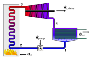 Flow diagram of the four main devices used in the
Rankine cycle
. 1) Feedwater pump 2) Boiler or steam generator 3) Turbine or engine 4) Condenser; where
Q
=heat and
W
=work. Most of the heat is rejected as waste.
Flow diagram of the four main devices used in the
Rankine cycle
. 1) Feedwater pump 2) Boiler or steam generator 3) Turbine or engine 4) Condenser; where
Q
=heat and
W
=work. Most of the heat is rejected as waste.
The Rankine cycle is the fundamental thermodynamic underpinning of the steam engine. The cycle is an arrangement of components as is typically used for simple power production, and uses the phase change of water (boiling water producing steam, condensing exhaust steam, producing liquid water)) to provide a practical heat/power conversion system. The heat is supplied externally to a closed loop with some of the heat added being converted to work and the waste heat being removed in a condenser. The Rankine cycle is used in virtually all steam power production applications. In the 1990s, Rankine steam cycles generated about 90% of all electric power used throughout the world, including virtually all
solar
,
biomass
,
coal
and
nuclear
power plants
. It is named after
William John Macquorn Rankine
, a Scottish
polymath
.
[70]
The Rankine cycle is sometimes referred to as a practical
Carnot cycle
because, when an efficient turbine is used, the
TS diagram
begins to resemble the Carnot cycle. The main difference is that heat addition (in the boiler) and rejection (in the condenser) are
isobaric
(constant pressure) processes in the Rankine cycle and
isothermal
(constant
temperature
) processes in the theoretical Carnot cycle. In this cycle, a pump is used to pressurize the working fluid which is received from the condenser as a liquid not as a gas. Pumping the working fluid in liquid form during the cycle requires a small fraction of the energy to transport it compared to the energy needed to compress the working fluid in gaseous form in a compressor (as in the
Carnot cycle
). The cycle of a reciprocating steam engine differs from that of turbines because of condensation and re-evaporation occurring in the cylinder or in the steam inlet passages.
The working fluid in a Rankine cycle can operate as a closed loop system, where the working fluid is recycled continuously, or may be an "open loop" system, where the exhaust steam is directly released to the atmosphere, and a separate source of water feeding the boiler is supplied. Normally water is the fluid of choice due to its favourable properties, such as non-toxic and unreactive chemistry, abundance, low cost, and its
thermodynamic properties
.
Mercury
is the working fluid in the
mercury vapor turbine
. Low boiling hydrocarbons can be used in a
binary cycle
.
[
citation needed
]
[71]
The steam engine contributed much to the development of thermodynamic theory; however, the only applications of scientific theory that influenced the steam engine were the original concepts of harnessing the power of steam and atmospheric pressure and knowledge of properties of heat and steam. The experimental measurements made by Watt on a model steam engine led to the development of the separate condenser. Watt independently discovered
latent heat
, which was confirmed by the original discoverer
Joseph Black
, who also advised Watt on experimental procedures. Watt was also aware of the change in the boiling point of water with pressure. Otherwise, the improvements to the engine itself were more mechanical in nature.
[18]
The thermodynamic concepts of the Rankine cycle did give engineers the understanding needed to calculate efficiency which aided the development of modern high-pressure and -temperature boilers and the steam turbine.
[
citation needed
]
Efficiency
[
edit
]
The efficiency of an engine cycle can be calculated by dividing the energy output of mechanical work that the engine produces by the energy put into the engine.
The historical measure of a steam engine's
energy efficiency
was its "duty". The concept of duty was first introduced by Watt in order to illustrate how much more efficient his engines were over the earlier
Newcomen designs
. Duty is the number of
foot-pounds
of
work
delivered by burning one
bushel
(94 pounds) of coal. The best examples of Newcomen designs had a duty of about 7 million, but most were closer to 5 million. Watt's original low-pressure designs were able to deliver duty as high as 25 million, but averaged about 17. This was a three-fold improvement over the average Newcomen design. Early Watt engines equipped with high-pressure steam improved this to 65 million.
[72]
No heat engine can be more efficient than the
Carnot cycle
, in which heat is moved from a high-temperature reservoir to one at a low temperature, and the efficiency depends on the temperature difference. For the greatest efficiency, steam engines should be operated at the highest steam temperature possible (
superheated steam
), and release the waste heat at the lowest temperature possible.
[
citation needed
]
The efficiency of a Rankine cycle is usually limited by the working fluid. Without the pressure reaching
supercritical
levels for the working fluid, the temperature range over which the cycle can operate is small; in steam turbines, turbine entry temperatures are typically 565 °C (the
creep
limit of stainless steel) and condenser temperatures are around 30 °C. This gives a theoretical
Carnot efficiency
of about 63% compared with an actual efficiency of 42% for a modern coal-fired power station. This low turbine entry temperature (compared with a
gas turbine
) is why the Rankine cycle is often used as a bottoming cycle in
combined-cycle gas turbine
power stations.
[
citation needed
]
One principal advantage the Rankine cycle holds over others is that during the compression stage relatively little work is required to drive the pump, the working fluid being in its liquid phase at this point. By condensing the fluid, the work required by the pump consumes only 1% to 3% of the turbine (or reciprocating engine) power and contributes to a much higher efficiency for a real cycle. The benefit of this is lost somewhat due to the lower heat addition temperature.
Gas turbines
, for instance, have turbine entry temperatures approaching 1500 °C. Nonetheless, the efficiencies of actual large steam cycles and large modern simple cycle gas turbines are fairly well matched.
[73]
In practice, a reciprocating steam engine cycle exhausting the steam to atmosphere will typically have an efficiency (including the boiler) in the range of 1?10%. However, with the addition of a condenser, Corliss valves, multiple expansion, and high steam pressure/temperature, it may be greatly improved. Historically into the range of 10?20%, and very rarely slightly higher.
[
citation needed
]
A modern, large electrical power station (producing several hundred megawatts of electrical output) with
steam reheat
,
economizer
etc. will achieve efficiency in the mid 40% range, with the most efficient units approaching 50% thermal efficiency.
[
citation needed
]
It is also possible to capture the waste heat using
cogeneration
in which the waste heat is used for heating a lower boiling point working fluid or as a heat source for district heating via saturated low-pressure steam.
[
citation needed
]
See also
[
edit
]
Notes
[
edit
]
- ^
This model was built by Samuel Pemberton between 1880 and 1890.
- ^
Landes
[20]
refers to Thurston's definition of an engine and Thurston's calling Newcomen's the "first true engine".
References
[
edit
]
- ^
American Heritage Dictionary of the English Language
(4th ed.). Houghton Mifflin Company. 2000.
- ^
"Who Invented the Steam Engine?"
.
Live Science
. 19 March 2014.
- ^
Mierisch, Robert Charles (May 2018).
"The History and Future of High Efficiency Steam Engines"
(PDF)
.
EHA Magazine
.
2
(8): 24?25 – via engineersaustralia.org.au.
- ^
Gebhardt, G.F. (1928).
Steam Power Plant Engineering
(6th ed.). USA: John Wiley and Sons, Inc. p. 405.
- ^
a
b
c
d
Wiser, Wendell H. (2000).
Energy resources: occurrence, production, conversion, use
. Birkhauser. p. 190.
ISBN
978-0-387-98744-6
.
- ^
Green, Don (1997).
Perry's Chemical Engineers' Handbook
(7th ed.). USA: McGraw-Hill. pp. 29?24.
ISBN
0-07-049841-5
.
- ^
"Spilling Products"
.
www.spilling.de
. 5 October 2023
. Retrieved
5 October
2023
.
- ^
"turbine"
.
Encyclopædia Britannica Online
. 18 July 2007.
- ^
"De Architectura"
: Chapter VI (paragraph 2)
from "Ten Books on Architecture" by
Vitruvius
(1st century BC), published 17, June, 08
[1]
accessed 2009-07-07
- ^
Ahmad Y Hassan
(1976).
Taqi al-Din and Arabic Mechanical Engineering
, pp. 34?35. Institute for the History of Arabic Science,
University of Aleppo
.
- ^
"University of Rochester, NY,
The growth of the steam engine
online history resource, chapter one"
. History.rochester.edu. Archived from
the original
on 24 July 2011
. Retrieved
3 February
2010
.
- ^
Garcia, Nicholas (2007).
Mas alla de la Leyenda Negra
. Valencia: Universidad de Valencia. pp. 443?54.
ISBN
978-84-370-6791-9
.
- ^
Lira, Carl T. (21 May 2013).
"The Savery Pump"
.
Introductory Chemical Engineering Thermodynamics
. Michigan State University
. Retrieved
11 April
2014
.
- ^
Hills 1989
, pp. 16?20
- ^
"LXXII. An engine for raising water by fire; being on improvement of saver'y construction, to render it capable of working itself, invented by Mr. De Moura of Portugal, F. R. S. Described by Mr. J. Smeaton".
Philosophical Transactions of the Royal Society of London
.
47
: 436?438. 1752.
doi
:
10.1098/rstl.1751.0073
.
S2CID
186208904
.
- ^
a
b
Landes 1969
.
- ^
Jenkins, Ryhs (1971) [First published 1936].
Links in the History of Engineering and Technology from Tudor Times
. Cambridge: The Newcomen Society at the Cambridge University Press.
ISBN
978-0-8369-2167-0
.
. Collected Papers of Rhys Jenkins, Former Senior Examiner in the British Patent Office.
- ^
Landes 1969
, p. 101.
- ^
Nuvolari, A; Verspagen, Bart; Tunzelmann, Nicholas (2003). "The Diffusion of the Steam Engine in Eighteenth-Century Britain. Applied Evolutionary Economics and the Knowledge-based Economy" (Document). Eindhoven, The Netherlands: Eindhoven Centre for Innovation Studies (ECIS). p. 3.
(Paper to be presented at 50th Annual North American Meetings of the Regional Science Association International 20?22 November 2003)
- ^
Galloway, Elajah (1828).
History of the Steam Engine
. London: B. Steill, Paternoster-Row. pp. 23?24.
- ^
Leupold, Jacob (1725).
Theatri Machinarum Hydraulicarum
. Leipzig: Christoph Zunkel.
- ^
Hunter & Bryant 1991
Duty comparison was based on a carefully conducted trial in 1778.
- ^
a
b
Rosen, William (2012).
The Most Powerful Idea in the World: A Story of Steam, Industry and Invention
. University of Chicago Press. p. 185.
ISBN
978-0-226-72634-2
.
- ^
a
b
c
d
Thomson, Ross (2009).
Structures of Change in the Mechanical Age: Technological Invention in the United States 1790?1865
. Baltimore, MD: The Johns Hopkins University Press. p.
34
.
ISBN
978-0-8018-9141-0
.
- ^
"The Pictorial History of Steam Power" J.T. Van Reimsdijk and Kenneth Brown, Octopus Books Limited 1989,
ISBN
0-7064-0976-0
, p. 30
- ^
Cowan, Ruth Schwartz (1997),
A Social History of American Technology
, New York: Oxford University Press, p. 74,
ISBN
978-0-19-504606-9
- ^
Dickinson, Henry W; Titley, Arthur (1934). "Chronology".
Richard Trevithick, the engineer and the man
. Cambridge, England: Cambridge University Press. p. xvi.
OCLC
637669420
.
- ^
The American Car since 1775, Pub. L. Scott. Baily, 1971, p. 18
- ^
Van Slyck, J.D. (1879).
New England Manufacturers and Manufactories
. volume 1. Van Slyck. p. 198.
- ^
Gordon, W.J. (1910).
Our Home Railways, volume one
. London: Frederick Warne and Co. pp. 7?9.
- ^
"Nation Park Service Steam Locomotive article with photo of Fitch Steam model and dates of construction as 1780?1790"
. Nps.gov. 14 February 2002
. Retrieved
3 November
2009
.
- ^
"Richard Trevithick's steam locomotive | Rhagor"
. Museumwales.ac.uk. Archived from
the original
on 15 April 2011
. Retrieved
3 November
2009
.
- ^
"Steam train anniversary begins"
.
BBC
. 21 February 2004
. Retrieved
13 June
2009
.
A south Wales town has begun months of celebrations to mark the 200th anniversary of the invention of the steam locomotive. Merthyr Tydfil was the location where, on 21 February 1804, Richard Trevithick took the world into the railway age when he set one of his high-pressure steam engines on a local iron master's tram rails
- ^
Garnett, A.F. (2005).
Steel Wheels
. Cannwood Press. pp. 18?19.
- ^
Young, Robert (2000).
Timothy Hackworth and the Locomotive
(reprint of 1923 ed.). Lewes, UK: the Book Guild Ltd.
- ^
Hamilton Ellis (1968).
The Pictorial Encyclopedia of Railways
. The Hamlyn Publishing Group. pp. 24?30.
- ^
Michael Reimer, Dirk Endisch:
Baureihe 52.80 ? Die rekonstruierte Kriegslokomotive
, GeraMond,
ISBN
3-7654-7101-1
- ^
Vaclav Smil (2005),
Creating the Twentieth Century: Technical Innovations of 1867?1914 and Their Lasting Impact
, Oxford University Press, p. 62,
ISBN
978-0-19-516874-7
, retrieved
3 January
2009
- ^
Hunter 1985
, pp. 495?96 Description of the Colt portable engine
- ^
McNeil 1990
See description of steam locomotives
- ^
Jerome, Harry (1934).
Mechanization in Industry, National Bureau of Economic Research
(PDF)
. pp. 166?67.
- ^
a
b
Peabody 1893
, p. 384.
- ^
"Fossil Energy: How Turbine Power Plants Work"
. Fossil.energy.gov. Archived from
the original
on 12 August 2011
. Retrieved
25 September
2011
.
- ^
Nick Robins,
The Coming of the Comet: The Rise and Fall of the Paddle Steamer
, Seaforth Publishing, 2012,
ISBN
1-4738-1328-X
, Chapter 4
- ^
Walter, John (2008).
"The Engine Indicator"
(PDF)
. pp. xxv?xxvi. Archived from
the original
(PDF)
on 10 March 2012.
- ^
Bennett, S. (1979).
A History of Control Engineering 1800?1930
. London: Peter Peregrinus Ltd.
ISBN
978-0-86341-047-5
.
- ^
Bennett 1979
- ^
Basic Mechanical Engineering by Mohan Sen p. 266
- ^
"Stirling | Internal Combustion Engine | Cylinder (Engine) | Free 30-day Trial"
.
Scribd
. Retrieved
21 May
2020
.
- ^
a
b
van Riemsdijk, John (1994).
Compound Locomotives
. Penrhyn, UK: Atlantic Transport Publishers. pp. 2?3.
ISBN
978-0-906899-61-8
.
- ^
Brooks, John.
Dreadnought Gunnery at the Battle of Jutland
. p. 14.
- ^
"Valves and Steamchest - Advanced Steam Traction"
. 3 June 2017
. Retrieved
19 June
2024
.
- ^
"Backfiring".
The Tractor Field Book: With Power Farm Equipment Specifications
. Chicago: Farm Implement News Company. 1928. pp. 108?109 [
108
].
- ^
Bell, A.M. (1950).
Locomotives
. London: Virtue and Company. pp. 61?63.
- ^
Seaton, A E (1918).
Manual of Marine Engineering
. London: Charles Griffin. pp. 56?108.
- ^
Steam Rockets
Archived
24 November 2019 at the
Wayback Machine
Tecaeromax
- ^
"William J. M. Rankine"
.
Scottish Engineering Hall of Fame
. Retrieved
13 December
2022
.
- ^
Parada, Angel Fernando Monroy (2013).
"GEOTHERMAL BINARY CYCLE POWER PLANT PRINCIPLES, OPERATION AND MAINTENANCE"
(PDF)
.
Orkustofnun (Islandic National Energy Authority)
. Retrieved
13 December
2022
.
- ^
John Enys,
"Remarks on the Duty of the Steam Engines employed in the Mines of Cornwall at different periods"
,
Transactions of the Institution of Civil Engineers
, Volume 3 (14 January 1840), p. 457
- ^
Yin, Feijia; Rao, Arvind Gangoli (1 February 2020).
"A review of gas turbine engine with inter-stage turbine burner"
.
Progress in Aerospace Sciences
.
121
: 100695.
Bibcode
:
2020PrAeS.12100695Y
.
doi
:
10.1016/j.paerosci.2020.100695
.
ISSN
0376-0421
.
S2CID
226624605
.
Books
[
edit
]
- Brown, Richard (2002).
Society and Economy in Modern Britain 1700?1850
. Taylor & Francis.
ISBN
978-0-203-40252-8
.
- Chapelon, Andre (2000) [1938].
La locomotive a vapeur
[
The Steam Locomotive
] (in French). Translated by Carpenter, George W. Camden Miniature Steam Services.
ISBN
978-0-9536523-0-3
.
- Ewing, Sir James Alfred (1894).
The Steam-engine and Other Heat-engines
. Cambridge: University Press.
- Hills, Richard L.
(1989).
Power from Steam: A history of the stationary steam engine
. Cambridge: Cambridge University Press.
ISBN
978-0-521-34356-5
.
- Hunter, Louis C. (1985).
A History of Industrial Power in the United States, 1730?1930
. Vol. 2: Steam Power. Charlottesville: University Press of Virginia.
- Hunter, Louis C.; Bryant, Lynwood (1991).
A History of Industrial Power in the United States, 1730?1930
. Vol. 3: The Transmission of Power. Cambridge, MA: MIT Press.
ISBN
978-0-262-08198-6
.
- Landes, David S.
(1969).
The Unbound Prometheus: Technological Change and Industrial Development in Western Europe from 1750 to the Present
. Cambridge; NY: Press Syndicate of the University of Cambridge.
ISBN
978-0-521-09418-4
.
- McNeil, Ian (1990).
An Encyclopedia of the History of Technology
. London: Routledge.
ISBN
978-0-415-14792-7
.
- Nag, P. K. (2002).
Power Plant Engineering
. Tata McGraw-Hill Education.
ISBN
978-0-07-043599-5
.
- Payton, Philip (2004). "Trevithick, Richard (1771?1833)".
Oxford Dictionary of National Biography
(online ed.). Oxford University Press.
doi
:
10.1093/ref:odnb/27723
.
(Subscription or
UK public library membership
required.)
- Peabody, Cecil Hobart (1893).
Thermodynamics of the Steam-engine and Other Heat-engines
. New York: Wiley & Sons.
Further reading
[
edit
]
- Crump, Thomas (2007).
A Brief History of the Age of Steam: From the First Engine to the Boats and Railways
.
- Ewing, James Alfred
(1911).
"Steam Engine"
.
Encyclopædia Britannica
. Vol. 25 (11th ed.). pp. 818?850.
- Marsden, Ben (2004).
Watt's Perfect Engine: Steam and the Age of Invention
. Columbia University Press.
- Robinson, Eric H. (March 1974). "The Early Diffusion of Steam Power".
The Journal of Economic History
.
34
(1): 91?107.
doi
:
10.1017/S002205070007964X
.
JSTOR
2116960
.
S2CID
153489574
.
- Rose, Joshua. (1887, reprint 2003)
Modern Steam Engines
- Stuart, Robert (1824).
A Descriptive History of the Steam Engine
. London: J. Knight and H. Lacey.
- Thurston, Robert Henry (1878).
A History of the Growth of the Steam-engine
. The International Scientific Series. New York: D. Appleton and Company.
OCLC
16507415
.
- Van Riemsdijk, J. T. (1980)
Pictorial History of Steam Power
.
- Charles Algernon Parsons
(1911),
The Steam Turbine: The Rede Lecture 1911
(1st ed.), Cambridge:
Cambridge University Press
,
Wikidata
Q19099885
(lecture)
External links
[
edit
]
|
|---|
| Stationary engines
| |
|---|
| Transport applications
| | Marine:
| |
|---|
| Rail:
| |
|---|
| Agriculture:
| |
|---|
| Road:
| |
|---|
| Construction:
| |
|---|
| Military:
| |
|---|
| Space and air:
| |
|---|
| Miscellaneous:
| |
|---|
|
|---|
| See also
| |
|---|