Radio communications concept
This article is about radio communications. For participation in other music projects, see
Side project
.
 The power of an AM radio signal plotted against frequency.
fc
is the
carrier frequency
,
fm
is the maximum modulation frequency
The power of an AM radio signal plotted against frequency.
fc
is the
carrier frequency
,
fm
is the maximum modulation frequency
In
radio
communications, a
sideband
is a
band
of
frequencies
higher than or lower than the
carrier frequency
, that are the result of the
modulation
process. The sidebands carry the information transmitted by the radio signal. The sidebands comprise all the
spectral components
of the modulated signal except the carrier. The signal components above the carrier frequency constitute the
upper sideband
(
USB
), and those below the carrier frequency constitute the
lower sideband
(
LSB
). All forms of modulation produce sidebands.
Sideband creation
[
edit
]
We can illustrate the creation of sidebands with one trigonometric identity
:

Adding
 to both sides
:
to both sides
:
![{\displaystyle \cos(A)\cdot [1+\cos(B)]={\tfrac {1}{2}}\cos(A+B)+\cos(A)+{\tfrac {1}{2}}\cos(A-B)}](https://wikimedia.org/api/rest_v1/media/math/render/svg/e74535a5163ade273c2ea320dc59dc9714790cfb)
Substituting (for instance)
 and
and
 where
where
 represents time
:
represents time
:
![{\displaystyle \underbrace {\cos(1000\ t)} _{\text{carrier wave}}\cdot \underbrace {[1+\cos(100\ t)]} _{\text{amplitude modulation}}=\underbrace {{\tfrac {1}{2}}\cos(1100\ t)} _{\text{upper sideband}}+\underbrace {\cos(1000\ t)} _{\text{carrier wave}}+\underbrace {{\tfrac {1}{2}}\cos(900\ t)} _{\text{lower sideband}}.}](https://wikimedia.org/api/rest_v1/media/math/render/svg/acfd1bddb1316e0f98379c1d0e558d7c3e1ad847)
Adding more complexity and time-variation to the amplitude modulation also adds it to the sidebands, causing them to widen in bandwidth and change with time. In effect, the sidebands "carry" the information content of the signal.
[1]
Sideband Characterization
[
edit
]
In the example above, a
cross-correlation
of the modulated signal with a pure sinusoid,
 is zero at all values of
 except 1100, 1000, and 900. And the non-zero values reflect the relative strengths of the three components. A graph of that concept, called a
Fourier transform
(or
spectrum
), is the customary way of visualizing sidebands and defining their parameters.
except 1100, 1000, and 900. And the non-zero values reflect the relative strengths of the three components. A graph of that concept, called a
Fourier transform
(or
spectrum
), is the customary way of visualizing sidebands and defining their parameters.
 Frequency
spectrum of a typical modulated AM or FM radio signal.
Frequency
spectrum of a typical modulated AM or FM radio signal.
Amplitude modulation
[
edit
]
Amplitude modulation
of a
carrier signal
normally results in two mirror-image sidebands. The signal components above the carrier frequency constitute the upper sideband (USB), and those below the carrier frequency constitute the lower sideband (LSB). For example, if a 900
kHz carrier is amplitude modulated by a 1
kHz audio signal, there will be components at 899
kHz and 901
kHz as well as 900
kHz in the generated
radio frequency
spectrum; so an
audio
bandwidth
of (say) 7
kHz will require a
radio spectrum
bandwidth of 14
kHz. In conventional AM
transmission
, as used by
broadcast band
AM stations, the original audio signal can be recovered ("detected") by either
synchronous detector
circuits or by simple
envelope detectors
because the carrier and both sidebands are present. This is sometimes called
double sideband amplitude modulation
(
DSB-AM
), but not all variants of DSB are compatible with envelope detectors.
In some forms of AM, the carrier may be reduced, to save power. The term
DSB reduced-carrier
normally implies enough carrier remains in the transmission to enable a
receiver
circuit to regenerate a strong carrier or at least
synchronise
a
phase-locked loop
but there are forms where the carrier is removed completely, producing
double sideband with
suppressed
carrier
(DSB-SC). Suppressed carrier systems require more sophisticated circuits in the receiver and some other method of deducing the original carrier frequency. An example is the
stereophonic
difference (L-R) information transmitted in stereo
FM broadcasting
on a 38 kHz
subcarrier
where a low-power signal at half the 38-kHz carrier frequency is inserted between the monaural signal frequencies (up to 15
kHz) and the bottom of the stereo information sub-carrier (down to 38?15
kHz, i.e. 23
kHz). The receiver locally regenerates the subcarrier by doubling a special 19 kHz
pilot tone
. In another example, the
quadrature modulation
used historically for chroma information in
PAL
television broadcasts, the synchronising signal is a short burst of a few cycles of carrier during the
"back porch"
part of each scan line when no image is transmitted. But in other DSB-SC systems, the carrier may be regenerated directly from the sidebands by a
Costas loop
or
squaring loop
. This is common in digital transmission systems such as
BPSK
where the signal is continually present.
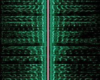 Sidebands are evident in this
spectrogram
of an AM broadcast (The carrier is highlighted in red, the two mirrored audio spectra (green) are the lower and upper sideband). Time is represented along the vertical axis; the magnitude and frequency of the side bands changes with the program content.
Sidebands are evident in this
spectrogram
of an AM broadcast (The carrier is highlighted in red, the two mirrored audio spectra (green) are the lower and upper sideband). Time is represented along the vertical axis; the magnitude and frequency of the side bands changes with the program content.
If part of one sideband and all of the other remain, it is called
vestigial sideband
, used mostly with
television
broadcasting
, which would otherwise take up an unacceptable amount of
bandwidth
. Transmission in which only one sideband is transmitted is called
single-sideband modulation
or SSB. SSB is the predominant voice mode on
shortwave radio
other than
shortwave broadcasting
. Since the sidebands are mirror images, which sideband is used is a matter of convention.
In SSB, the
carrier is suppressed
, significantly reducing the
electrical power
(by up to 12
dB) without affecting the information in the sideband. This makes for more efficient use of transmitter power and RF bandwidth, but a
beat frequency oscillator
must be used at the
receiver
to reconstitute the carrier. If the reconstituted carrier frequency is wrong then the output of the receiver will have the wrong frequencies, but for speech small frequency errors are no problem for intelligibility. Another way to look at an SSB receiver is as an RF-to-audio frequency
transposer
: in USB mode, the dial frequency is subtracted from each radio frequency component to produce a corresponding audio component, while in LSB mode each incoming radio frequency component is subtracted from the dial frequency.
Frequency modulation
[
edit
]
Frequency modulation
also generates sidebands, the bandwidth consumed depending on the
modulation index
- often requiring significantly more bandwidth than DSB.
Bessel functions
can be used to calculate the bandwidth requirements of FM transmissions.
Carson's rule
is a useful approximation of bandwidth in several applications.
Effects
[
edit
]
Sidebands can
interfere
with
adjacent channels
. The part of the sideband that would overlap the neighboring channel must be suppressed by
filters
, before or after modulation (often both). In
broadcast band
frequency modulation
(FM),
subcarriers
above 75
kHz
are limited to a small
percentage
of modulation and are prohibited above 99 kHz altogether to protect the ±75 kHz normal
deviation
and ±100 kHz
channel
boundaries.
Amateur radio
and public service FM transmitters generally utilize ±5 kHz deviation.
To accurately reproduce the modulating waveform, the entire signal processing path of the system of transmitter, propagation path, and receiver must have enough bandwidth so that enough of the sidebands can be used to recreate the modulated signal to the desired degree of accuracy.
In a non-linear system such as an amplifier, sidebands of the original signal frequency components may be generated due to distortion. This is generally minimized but may be intentionally done for the
fuzzbox
musical effect.
See also
[
edit
]
References
[
edit
]
- ^
Tony Dorbuck (ed.),
The Radio Amateur's Handbook, Fifty-Fifth Edition
, American Radio Relay League, 1977, p. 368