Analog television system
 Analog television encoding systems by nation; NTSC (
green
),
SECAM
(
orange
), and
PAL
(
blue
)
Analog television encoding systems by nation; NTSC (
green
),
SECAM
(
orange
), and
PAL
(
blue
)
NTSC
(from
National Television Standards Committee
) is the first American standard for
analog television
, published in 1941.
[1]
In 1961, it was assigned the designation
System M
. It is also known as
EIA
standard 170.
[2]
In 1953, a second NTSC standard was adopted, which allowed for
color television
broadcast compatible with the existing stock of
black-and-white
receivers. It is one of three major color formats for analog television, the others being
PAL
and
SECAM
.
NTSC color
is usually associated with the System M; this combination is sometimes called NTSC II.
[3]
[4]
The only other
broadcast television system
to use NTSC color was the
System J
. Brazil used System M with PAL color. Vietnam, Cambodia and Laos used System M with SECAM color - Vietnam later started using PAL in the early 1990s.
The NTSC/System M standard was used in most of the
Americas
(except
Argentina
,
Brazil
,
Paraguay
, and
Uruguay
),
Myanmar
,
South Korea
,
Taiwan
,
Philippines
,
Japan
, and some
Pacific Islands
nations and territories (see map).
Since the introduction of digital sources (ex: DVD) the term
NTSC
has been used to refer to digital formats with number of active lines between 480 and 487 having 30 or 29.97 frames per second rate, serving as a digital shorthand to System M. The so-called
NTSC-Film
standard
has a digital standard resolution of 720 × 480 pixel for
DVD-Videos
, 480 × 480 pixel for
Super Video CDs
(SVCD, Aspect Ratio: 4:3) and 352 × 240 pixel for
Video CDs
(VCD).
[5]
The
digital video
(DV) camcorder format that is equivalent to NTSC is 720 × 480 pixels.
[6]
The
digital television
(DTV) equivalent is 704 × 480 pixels.
[6]
History
[
edit
]
The National Television System Committee was established in 1940 by the United States
Federal Communications Commission
(FCC) to resolve the conflicts between companies over the introduction of a nationwide analog television system in the United States. In March 1941, the committee issued a technical standard for black-and-white television that built upon a 1936 recommendation made by the Radio Manufacturers Association (RMA). Technical advancements of the
vestigial side band
technique allowed for the opportunity to increase the image resolution. The NTSC selected 525 scan lines as a compromise between
RCA
's
441-scan line
standard (already being used by RCA's
NBC
TV network) and
Philco
's and
DuMont
's desire to increase the number of scan lines to between 605 and 800.
[7]
The standard recommended a
frame rate
of 30 frames (images) per second, consisting of two
interlaced
fields
per frame at 262.5 lines per field and 60 fields per second. Other standards in the final recommendation were an
aspect ratio
of 4:3, and frequency modulation (FM) for the sound signal (which was quite new at the time).
In January 1950, the committee was reconstituted to standardize
color television
. The FCC had briefly approved a
405-line
field-sequential
color television standard in October 1950, which was developed by
CBS
.
[8]
The CBS system was incompatible with existing black-and-white receivers. It used a rotating color wheel, reduced the number of
scan lines
from 525 to 405, and increased the field rate from 60 to 144, but had an effective
frame rate
of only 24 frames per second. Legal action by rival RCA kept commercial use of the system off the air until June 1951, and regular broadcasts only lasted a few months before manufacture of all color television sets was banned by the
Office of Defense Mobilization
in October, ostensibly due to the
Korean War
.
[9]
[10]
[11]
[12]
A variant of the CBS system was later used by
NASA
to broadcast pictures of astronauts from space.
[
citation needed
]
CBS rescinded its system in March 1953,
[13]
and the FCC replaced it on December 17, 1953, with the NTSC color standard, which was cooperatively developed by several companies, including RCA and Philco.
[14]
In December 1953, the FCC unanimously approved what is now called the
NTSC
color television standard (later defined as RS-170a). The compatible color standard retained full backward compatibility with then-existing black-and-white television sets. Color information was added to the black-and-white image by introducing a color
subcarrier
of precisely 315/88 MHz (usually described as 3.579545 MHz±10 Hz).
[15]
The precise frequency was chosen so that horizontal line-rate modulation components of the chrominance signal fall exactly in between the horizontal line-rate modulation components of the luminance signal, such that the chrominance signal could easily be filtered out of the luminance signal on new television sets, and that it would be minimally visible in existing televisions. Due to limitations of
frequency divider
circuits at the time the color standard was promulgated, the color subcarrier frequency was constructed as composite frequency assembled from small integers, in this case 5×7×9/(8×11) MHz.
[16]
The horizontal line rate was reduced to approximately 15,734 lines per second (3.579545×2/455 MHz = 9/572 MHz) from 15,750 lines per second, and the frame rate was reduced to 30/1.001 ? 29.970 frames per second (the horizontal line rate divided by 525 lines/frame) from 30 frames per second. These changes amounted to 0.1 percent and were readily tolerated by then-existing television receivers.
[17]
[18]
The first publicly announced network television broadcast of a program using the NTSC "compatible color" system was an episode of NBC's
Kukla, Fran and Ollie
on August 30, 1953, although it was viewable in color only at the network's headquarters.
[19]
The first nationwide viewing of NTSC color came on the following January 1 with the coast-to-coast broadcast of the
Tournament of Roses Parade
, viewable on prototype color receivers at special presentations across the country. The first color NTSC
television camera
was the
RCA TK-40
, used for experimental broadcasts in 1953; an improved version, the TK-40A, introduced in March 1954, was the first commercially available color television camera. Later that year, the improved TK-41 became the standard camera used throughout much of the 1960s.
The NTSC standard has been adopted by other countries, including some in the
Americas
and
Japan
.
With the advent of
digital television
, analog broadcasts were largely phased out. Most US NTSC broadcasters were required by the FCC to shut down their analog transmitters by February 17, 2009, however this was later moved to June 12, 2009.
Low-power stations
,
Class A stations
and
translators
were required to shut down by 2015, although an FCC extension allowed some of those stations operating on Channel 6 to operate until July 13, 2021.
[20]
The remaining Canadian analog TV transmitters, in markets not subject to the mandatory transition in 2011, were scheduled to be shut down by January 14, 2022, under a schedule published by
Innovation, Science and Economic Development Canada
in 2017; however the scheduled transition dates have already passed for several stations listed that continue to broadcast in analog (e.g.
CFJC-TV
Kamloops, which has not yet transitioned to digital, is listed as having been required to transition by November 20, 2020).
[21]
Digital conversion
[
edit
]
Most countries using the NTSC standard, as well as those using other
analog television standards
, have switched to, or are in process of switching to, newer
digital television
standards, with there being at least four different standards in use around the world. North America, parts of
Central America
, and
South Korea
are adopting or have adopted the
ATSC
standards, while other countries, such as
Japan
, are adopting or have adopted other standards instead of ATSC. After nearly 70 years, the majority of over-the-air NTSC transmissions in the United States ceased on June 12, 2009,
[22]
and by August 31, 2011,
[23]
in
Canada
and most other NTSC markets.
[24]
The majority of NTSC transmissions ended in Japan on July 24, 2011, with the Japanese prefectures of
Iwate
,
Miyagi
, and
Fukushima
ending the next year.
[23]
After a pilot program in 2013, most full-power analog stations in Mexico left the air on ten dates in 2015, with some 500 low-power and repeater stations allowed to remain in analog until the end of 2016. Digital broadcasting allows
higher-resolution television
, but
digital standard definition television
continues to use the frame rate and number of lines of resolution established by the analog NTSC standard.
Technical details
[
edit
]
Resolution and refresh rate
[
edit
]
NTSC color encoding is used with the
System M
television signal, which consists of
30
⁄
1.001
(approximately 29.97)
interlaced
frames of
video
per
second
. Each frame is composed of two fields, each consisting of 262.5 scan lines, for a total of 525 scan lines. The visible
raster
is made up of 486 scan lines. The later digital standard,
Rec. 601
, only uses 480 of these lines for visible raster. The remainder (the
vertical blanking interval
) allow for vertical
synchronization
and retrace. This blanking interval was originally designed to simply blank the electron beam of the receiver's CRT to allow for the simple analog circuits and slow vertical retrace of early TV receivers. However, some of these lines may now contain other data such as
closed captioning
and vertical interval
timecode
(VITC). In the complete
raster
(disregarding half lines due to
interlacing
) the even-numbered scan lines (every other line that would be even if counted in the video signal, e.g. {2, 4, 6, ..., 524}) are drawn in the first field, and the odd-numbered (every other line that would be odd if counted in the video signal, e.g. {1, 3, 5, ..., 525}) are drawn in the second field, to yield a
flicker-free
image at the field refresh
frequency
of
60
⁄
1.001
Hz (approximately 59.94 Hz). For comparison, 625 lines (576 visible) systems, usually used with
PAL-B/G
and
SECAM
color, and so have a higher vertical resolution, but a lower temporal resolution of 25 frames or 50 fields per second.
The NTSC field refresh frequency in the black-and-white system originally exactly matched the nominal 60 Hz
frequency
of
alternating current
power used in the United States. Matching the field
refresh rate
to the power source avoided
intermodulation
(also called
beating
), which produces rolling bars on the screen. Synchronization of the refresh rate to the power incidentally helped
kinescope
cameras record early live television broadcasts, as it was very simple to synchronize a
film
camera to capture one frame of video on each film frame by using the alternating current frequency to set the speed of the synchronous AC motor-drive camera. This, as mentioned, is how the NTSC field refresh frequency worked in the original black-and-white system; when
color
was added to the system, however, the refresh frequency was shifted slightly downward by 0.1%, to approximately 59.94 Hz, to eliminate stationary dot patterns in the difference frequency between the sound and color carriers (as explained below in
§
Color encoding
). By the time the frame rate changed to accommodate color, it was nearly as easy to trigger the camera shutter from the video signal itself.
The actual figure of 525 lines was chosen as a consequence of the limitations of the vacuum-tube-based technologies of the day. In early TV systems, a master
voltage-controlled oscillator
was run at twice the horizontal line frequency, and this
frequency was divided
down by the number of lines used (in this case 525) to give the field frequency (60 Hz in this case). This frequency was then compared with the 60 Hz
power-line frequency
and any discrepancy
corrected by adjusting the frequency
of the master oscillator. For interlaced scanning, an odd number of lines per frame was required in order to make the vertical retrace distance identical for the odd and even fields,
[
clarification needed
]
which meant the master oscillator frequency had to be divided down by an odd number. At the time, the only practical method of frequency division was the use of a chain of
vacuum tube
multivibrators
, the overall division ratio being the mathematical product of the division ratios of the chain. Since all the factors of an odd number also have to be odd numbers, it follows that all the dividers in the chain also had to divide by odd numbers, and these had to be relatively small due to the problems of
thermal drift
with vacuum tube devices. The closest practical sequence to 500 that meets these criteria was
3×5×5×7=525
. (For the same reason, 625-line PAL-B/G and SECAM uses
5×5×5×5
, the old
British 405-line system
used
3×3×3×3×5
, the French
819-line
system used
3×3×7×13
etc.)
Colorimetry
[
edit
]
 NTSC 1953 colorimetry color cube (color profile encoded, requires a compatible browser and monitor for accurate display).
The original 1953 color NTSC specification, still part of the United States
Code of Federal Regulations
, defined the
colorimetric
values of the system as follows:
[25]
Early color television receivers, such as the RCA
CT-100
, were faithful to this specification (which was based on prevailing motion picture standards), having a larger gamut than most of today's monitors. Their low-efficiency phosphors (notably in the Red) were weak and long-persistent, leaving trails after moving objects. Starting in the late 1950s, picture tube phosphors would sacrifice saturation for increased brightness; this deviation from the standard at both the receiver and broadcaster was the source of considerable color variation.
SMPTE C
[
edit
]
 SMPTE C color cube (color profile encoded, requires a compatible browser and monitor for accurate display).
To ensure more uniform color reproduction, receivers started to incorporate color correction circuits that converted the received signal?encoded for the colorimetric values listed above?into signals encoded for the phosphors actually used within the monitor. Since such color correction can not be performed accurately on the nonlinear
gamma corrected
signals transmitted, the adjustment can only be approximated, introducing both hue and
luminance
errors for highly saturated colors.
Similarly at the broadcaster stage, in 1968?69 the Conrac Corp., working with RCA, defined a set of controlled phosphors for use in broadcast color picture
video monitors
.
[26]
This specification survives today as the
SMPTE "C"
phosphor specification:
As with home receivers, it was further recommended
[27]
that studio monitors incorporate similar color correction circuits so that broadcasters would transmit pictures encoded for the original 1953 colorimetric values, in accordance with FCC standards.
In 1987, the
Society of Motion Picture and Television Engineers
(SMPTE) Committee on Television Technology, Working Group on Studio Monitor Colorimetry, adopted the SMPTE C (Conrac) phosphors for general use in Recommended Practice 145,
[28]
prompting many manufacturers to modify their camera designs to directly encode for SMPTE "C" colorimetry without color correction,
[29]
as approved in SMPTE standard 170M, "Composite Analog Video Signal ? NTSC for Studio Applications" (1994). As a consequence, the
ATSC
digital television standard states that for
480i
signals, SMPTE "C" colorimetry should be assumed unless colorimetric data is included in the transport stream.
[30]
Japanese NTSC never changed primaries and whitepoint to SMPTE "C", continuing to use the 1953 NTSC primaries and whitepoint.
[27]
Both the
PAL
and
SECAM
systems used the original 1953 NTSC colorimetry as well until 1970;
[27]
unlike NTSC, however, the European Broadcasting Union (EBU) rejected color correction in receivers and studio monitors that year and instead explicitly called for all equipment to directly encode signals for the "EBU" colorimetric values,
[31]
further improving the color fidelity of those systems.
Color encoding
[
edit
]
For backward compatibility with black-and-white television, NTSC uses a
luminance
-
chrominance
encoding system invented in 1938 by
Georges Valensi
. The
three
color picture signals are divided into Luminance (derived mathematically from the three separate color signals (Red, Green and Blue))
[32]
which takes the place of the original
monochrome signal
and Chrominance which carries
only
the color information. This process is applied to
each
color source by its own
Colorplexer
,
[33]
[34]
thereby allowing a compatible color source to be managed as if it were an ordinary monochrome source. This allows black-and-white receivers to display NTSC color signals by simply ignoring the chrominance signal. Some black-and-white TVs sold in the U.S. after the introduction of color broadcasting in 1953 were designed to filter chroma out, but the early B&W sets did not do this and
chrominance
could be seen as a 'dot pattern' in highly colored areas of the picture, called
dot crawl
.
[35]
In NTSC, chrominance is encoded using two color signals known as I (in-phase) and Q (in quadrature) in a process called
QAM
. The two signals each amplitude modulate
[36]
3.58 MHz carriers which are 90 degrees out of phase with each other
[37]
and the result added together but with the
carriers themselves being suppressed
.
[38]
[36]
The result can be viewed as a single sine wave with varying phase relative to a reference carrier and with varying amplitude. The varying phase represents the instantaneous
color hue
captured by a TV camera, and the amplitude represents the instantaneous
color saturation
. This 3.579545 MHz
subcarrier
is then added to the Luminance to form the
composite color signal
[36]
which modulates the video signal
carrier
just as in monochrome transmission. 3.58 MHz is often mentioned instead of 3.579545 MHz.
[39]
For a color TV to recover hue information from the color subcarrier, it must have a zero-phase reference to replace the previously suppressed carrier. The NTSC signal includes a short sample of this reference signal, known as the
colorburst
, located on the
back porch
of each horizontal synchronization pulse. The color burst consists of a minimum of eight cycles of the unmodulated (fixed phase and amplitude) color subcarrier. The TV receiver has a
local oscillator
, which is synchronized with these color bursts. Combining this reference phase signal derived from the color burst with the chrominance signal's amplitude and phase allows the recovery of the I and Q signals which when combined with the luminance information allows the reconstruction of a color image on the screen. Color TV has been said to really be color
ed
TV because of the total separation of the brightness part of the picture from the color portion. In CRT televisions, the NTSC signal is turned into three color signals: red green and blue, each controlling that color electron gun. TV sets with digital circuitry use sampling techniques to process the signals but the result is the same. For both analog and digital sets processing an analog NTSC signal, the original three color signals are transmitted using three discrete signals (luminance, I and Q) and then recovered as three separate colors and combined as a color image.
When a transmitter broadcasts an NTSC signal, it amplitude-modulates a radio-frequency carrier with the NTSC signal just described, while it frequency-modulates a carrier 4.5 MHz higher with the audio signal. If non-linear distortion happens to the broadcast signal, the 3.579545 MHz color carrier may
beat
with the sound carrier to produce a dot pattern on the screen. To make the resulting pattern less noticeable, designers adjusted the original 15,750 Hz scanline rate down by a factor of 1.001 (0.1%) to match the audio carrier frequency divided by the factor 286, resulting in a field rate of approximately 59.94 Hz. This adjustment ensures that the difference between the sound carrier and the color subcarrier (the most problematic
intermodulation
product of the two carriers) is an odd multiple of half the line rate, which is the necessary condition for the dots on successive lines to be opposite in phase, making them least noticeable.
The 59.94 rate is derived from the following calculations. Designers chose to make the chrominance subcarrier frequency an
n
+ 0.5 multiple of the line frequency to minimize interference between the luminance signal and the chrominance signal. (Another way this is often stated is that the color subcarrier frequency is an odd multiple of half the line frequency.) They then chose to make the audio subcarrier frequency an integer multiple of the line frequency to minimize visible (intermodulation) interference between the audio signal and the chrominance signal. The original black-and-white standard, with its 15,750 Hz line frequency and 4.5 MHz audio subcarrier, does not meet these requirements, so designers had to either raise the audio subcarrier frequency or lower the line frequency. Raising the audio subcarrier frequency would prevent existing (black and white) receivers from properly tuning in the audio signal. Lowering the line frequency is comparatively innocuous, because the horizontal and vertical synchronization information in the NTSC signal allows a receiver to tolerate a substantial amount of variation in the line frequency. So the engineers chose the line frequency to be changed for the color standard. In the black-and-white standard, the ratio of audio subcarrier frequency to line frequency is
4.5 MHz
⁄
15,750 Hz
= 285.71. In the color standard, this becomes rounded to the integer 286, which means the color standard's line rate is
4.5 MHz
⁄
286
≈ 15,734 Hz. Maintaining the same number of scan lines per field (and frame), the lower line rate must yield a lower field rate. Dividing
4500000
⁄
286
lines per second by 262.5 lines per field gives approximately 59.94 fields per second.
Transmission modulation method
[
edit
]
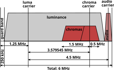 Spectrum of a System M television channel with NTSC color
An NTSC
television channel
as transmitted occupies a total bandwidth of 6 MHz. The actual video signal, which is
amplitude-modulated
, is transmitted between 500
kHz
and 5.45 MHz above the lower bound of the channel. The video
carrier
is 1.25 MHz above the lower bound of the channel. Like most AM signals, the video carrier generates two
sidebands
, one above the carrier and one below. The sidebands are each 4.2 MHz wide. The entire upper sideband is transmitted, but only 1.25 MHz of the lower sideband, known as a
vestigial sideband
, is transmitted. The color subcarrier, as noted above, is 3.579545 MHz above the video carrier, and is
quadrature-amplitude-modulated
with a suppressed carrier. The audio signal is
frequency-modulated
, like the audio signals broadcast by
FM radio
stations
in the 88?108 MHz band, but with a 25 kHz maximum
frequency deviation
, as opposed to 75 kHz as is used on the
FM band
, making analog television audio signals sound quieter than FM radio signals as received on a wideband receiver. The main audio carrier is 4.5 MHz above the video carrier, making it 250 kHz below the top of the channel. Sometimes a channel may contain an
MTS
signal, which offers more than one audio signal by adding one or two subcarriers on the audio signal, each synchronized to a multiple of the line frequency. This is normally the case when
stereo audio
and/or
second audio program
signals are used. The same extensions are used in
ATSC
, where the ATSC digital carrier is broadcast at 0.31 MHz above the lower bound of the channel.
"Setup" is a 54 mV (7.5
IRE
) voltage offset between the "black" and "blanking" levels. It is unique to NTSC. CVBS stands for Color, Video, Blanking, and Sync.
The following table shows the values for the basic RGB colors, encoded in NTSC
[40]
Analog signal values for basic RGB colors, encoded in NTSC
| Color
|
Luminance
level (
IRE
)
|
Chrominance
level (IRE)
|
Chrominance amplitude (IRE)
|
Phase (º)
|
| White
|
100.0
|
0.0
|
0.0
|
?
|
| Yellow
|
89.5
|
48.1 to 130.8
|
82.7
|
167.1
|
| Cyan
|
72.3
|
13.9 to 130.8
|
116.9
|
283.5
|
| Green
|
61.8
|
7.2 to 116.4
|
109.2
|
240.7
|
| Magenta
|
45.7
|
?8.9 to 100.3
|
109.2
|
60.7
|
| Red
|
35.2
|
?23.3 to 93.6
|
116.9
|
103.5
|
| Blue
|
18.0
|
?23.3 to 59.4
|
82.7
|
347.1
|
| Black
|
7.5
|
0.0
|
0.0
|
?
|
Frame rate conversion
[
edit
]
There is a large difference in
frame rate
between film, which runs at 24.0 frames per second, and the NTSC standard, which runs at approximately 29.97 (10 MHz×63/88/455/525) frames per second.
In regions that use 25-fps television and video standards, this difference can be overcome by
speed-up
.
For 30-fps standards, a process called "
3:2 pulldown
" is used. One film frame is transmitted for three video fields (lasting
1
+
1
⁄
2
video frames), and the next frame is transmitted for two video fields (lasting 1 video frame). Two film frames are thus transmitted in five video fields, for an average of
2
+
1
⁄
2
video fields per film frame. The average frame rate is thus 60 ÷ 2.5 = 24 frames per second, so the average film speed is nominally exactly what it should be. (In reality, over the course of an hour of real time, 215,827.2 video fields are displayed, representing 86,330.88 frames of film, while in an hour of true 24-fps film projection, exactly 86,400 frames are shown: thus, 29.97-fps NTSC transmission of 24-fps film runs at 99.92% of the film's normal speed.) Still-framing on playback can display a video frame with fields from two different film frames, so any difference between the frames will appear as a rapid back-and-forth flicker. There can also be noticeable jitter/"stutter" during slow camera pans (
telecine judder
).
Film shot specifically for NTSC television is usually taken at 30 (instead of 24) frames per second to avoid 3:2 pulldown.
[41]
To show 25-fps material (such as European
television series
and some European movies) on NTSC equipment, every fifth frame is duplicated and then the resulting stream is interlaced.
Film shot for NTSC television at 24 frames per second has traditionally been accelerated by 1/24 (to about 104.17% of normal speed) for transmission in regions that use 25-fps television standards. This increase in picture speed has traditionally been accompanied by a similar increase in the pitch and tempo of the audio. More recently, frame-blending has been used to convert 24 FPS video to 25 FPS without altering its speed.
Film shot for television in regions that use 25-fps television standards can be handled in either of two ways:
- The film can be shot at 24 frames per second. In this case, when transmitted in its native region, the film may be accelerated to 25 fps according to the analog technique described above, or kept at 24 fps by the digital technique described above. When the same film is transmitted in regions that use a nominal 30-fps television standard, there is no noticeable change in speed, tempo, and pitch.
- The film can be shot at 25 frames per second. In this case, when transmitted in its native region, the film is shown at its normal speed, with no alteration of the accompanying soundtrack. When the same film is shown in regions that use a 30-fps nominal television standard, every fifth frame is duplicated, and there is still no noticeable change in speed, tempo, and pitch.
Because both film speeds have been used in 25-fps regions, viewers can face confusion about the true speed of video and audio, and the pitch of voices, sound effects, and musical performances, in television films from those regions. For example, they may wonder whether the
Jeremy Brett
series of
Sherlock Holmes
television films, made in the 1980s and early 1990s, was shot at 24 fps and then transmitted at an artificially fast speed in 25-fps regions, or whether it was shot at 25 fps natively and then slowed to 24 fps for NTSC exhibition.
These discrepancies exist not only in television broadcasts over the air and through cable, but also in the home-video market, on both tape and disc, including
laser disc
and
DVD
.
In digital television and video, which are replacing their analog predecessors, single standards that can accommodate a wider range of frame rates still show the limits of analog regional standards. The initial version of the
ATSC
standard, for example, allowed frame rates of 23.976, 24, 29.97, 30, 59.94, 60, 119.88 and 120 frames per second, but not 25 and 50. Modern ATSC allows 25 and 50 FPS.
Modulation for analog satellite transmission
[
edit
]
Because satellite power is severely limited, analog video transmission through satellites differs from terrestrial TV transmission.
AM
is a linear modulation method, so a given demodulated
signal-to-noise ratio
(SNR) requires an equally high received RF SNR. The SNR of studio quality video is over 50 dB, so AM would require prohibitively high powers and/or large antennas.
Wideband
FM
is used instead to trade RF bandwidth for reduced power. Increasing the channel bandwidth from 6 to 36 MHz allows a RF SNR of only 10 dB or less. The wider noise bandwidth reduces this 40 dB power saving by 36 MHz / 6 MHz = 8 dB for a substantial net reduction of 32 dB.
Sound is on an FM subcarrier as in terrestrial transmission, but frequencies above 4.5 MHz are used to reduce aural/visual interference. 6.8, 5.8 and 6.2 MHz are commonly used. Stereo can be multiplex, discrete, or matrix and unrelated audio and data signals may be placed on additional subcarriers.
A triangular 60 Hz energy dispersal waveform is added to the composite baseband signal (video plus audio and data subcarriers) before modulation. This limits the satellite downlink
power spectral density
in case the video signal is lost. Otherwise the satellite might transmit all of its power on a single frequency, interfering with terrestrial microwave links in the same frequency band.
In half transponder mode, the frequency deviation of the composite baseband signal is reduced to 18 MHz to allow another signal in the other half of the 36 MHz transponder. This reduces the FM benefit somewhat, and the recovered SNRs are further reduced because the combined signal power must be "backed off" to avoid intermodulation distortion in the satellite transponder. A single FM signal is constant amplitude, so it can saturate a transponder without distortion.
Field order
[
edit
]
An NTSC
frame
consists of two
fields,
F1 (field one) and F2 (field two). The
field dominance
depends on a combination of factors, including decisions by various equipment manufacturers as well as historical conventions. As a result, most professional equipment has the option to switch between a dominant upper or dominant lower field. It is not advisable to use the terms
even
or
odd
when speaking of fields, due to substantial ambiguity. For instance if the line numbering for a particular system starts at zero, while another system starts its line numbering at one. As such the same field could be even or odd.
[22]
[42]
While an analog television set does not care about field dominance per se, field dominance is important when editing NTSC video. Incorrect interpretation of field order can cause a shuddering effect as moving objects jump forward and behind on each successive field.
This is of particular importance when interlaced NTSC is transcoded to a format with a different field dominance and vice versa. Field order is also important when transcoding progressive video to interlaced NTSC, as any place there is a cut between two scenes in the progressive video, there could be a flash field in the interlaced video if the field dominance is incorrect. The film telecine process where a
three-two pull down
is utilized to convert 24 frames to 30, will also provide unacceptable results if the field order is incorrect.
Because each field is temporally unique for material captured with an interlaced camera, converting interlaced to a digital progressive-frame medium is difficult, as each progressive frame will have artifacts of motion on every alternating line. This can be observed in PC-based video-playing utilities and is frequently solved simply by transcoding the video at half resolution and only using one of the two available fields.
Variants
[
edit
]
NTSC-M
[
edit
]
Unlike PAL and SECAM, with its many varied underlying
broadcast television systems
in use throughout the world, NTSC color encoding is almost invariably used with
broadcast system
M
, giving NTSC-M.
NTSC-N and NTSC-50
[
edit
]
NTSC-N was originally proposed in the 1960s to the
CCIR
as a 50 Hz broadcast method for
System N
countries Paraguay, Uruguay and Argentina before they chose
PAL
. In the mid 1980s, it was effectively reintroduced as NTSC-50, a pseudo-system combining 625-line video with 3.58 MHz NTSC color. For example, an
Atari ST
running PAL software on their NTSC color display used this system as the monitor could not decode PAL color. Most analog NTSC television sets and monitors with a V-Hold knob can display this system after adjusting the vertical hold.
[43]
NTSC-J
[
edit
]
Only
Japan
's variant "
NTSC-J
" is slightly different: in Japan, black level and blanking level of the signal are identical (at 0
IRE
), as they are in PAL, while in American NTSC, black level is slightly higher (7.5
IRE
) than blanking level. Since the difference is quite small, a slight turn of the brightness knob is all that is required to correctly show the "other" variant of NTSC on any set as it is supposed to be; most watchers might not even notice the difference in the first place. The channel encoding on NTSC-J differs slightly from NTSC-M. In particular, the Japanese VHF band runs from channels 1?12 (located on frequencies directly above the 76?90 MHz Japanese
FM radio
band) while the North American VHF TV band uses channels 2?13 (54?72 MHz, 76?88 MHz and 174?216 MHz) with 88?108 MHz allocated to FM radio broadcasting. Japan's UHF TV channels are therefore numbered from 13 up and not 14 up, but otherwise uses the same UHF broadcasting frequencies as those in
North America
.
NTSC 4.43
[
edit
]
NTSC 4.43 is a pseudo-system that transmits a NTSC color subcarrier of 4.43 MHz instead of 3.58 MHz
[44]
The resulting output is only viewable by TVs that support the resulting pseudo-system (such as most PAL TVs).
[45]
Using a native NTSC TV to decode the signal yields no color, while using an incompatible PAL TV to decode the system yields erratic colors (observed to be lacking red and flickering randomly). The format was used by the
USAF
TV based in Germany during the
Cold War
and
Hong Kong Cable Television
.
[
citation needed
]
It was also found as an optional output on some
LaserDisc
players and some game consoles sold in markets where the PAL system is used.
The NTSC 4.43 system, while not a broadcast format, appears most often as a playback function of PAL cassette format VCRs, beginning with the Sony 3/4" U-Matic format and then following onto Betamax and VHS format machines, commonly advertised as "NTSC playback on PAL TV". As Hollywood has the claim of providing the most cassette software (movies and television series) for VCRs for the world's viewers, and as not
all
cassette releases were made available in PAL formats, a means of playing NTSC format cassettes was highly desired.
Multi-standard video monitors were already in use in Europe to accommodate broadcast sources in PAL, SECAM, and NTSC video formats. The
heterodyne
color-under process of U-Matic, Betamax & VHS lent itself to minor modification of VCR players to accommodate NTSC format cassettes. The color-under format of VHS uses a 629 kHz subcarrier while U-Matic & Betamax use a 688 kHz subcarrier to carry an
amplitude modulated
chroma signal for both NTSC and PAL formats. Since the VCR was ready to play the color portion of the NTSC recording using PAL color mode, the PAL scanner and capstan speeds had to be adjusted from PAL's 50 Hz field rate to NTSC's 59.94 Hz field rate, and faster linear tape speed.
The changes to the PAL VCR are minor thanks to the existing VCR recording formats. The output of the VCR when playing an NTSC cassette in NTSC 4.43 mode is 525 lines/29.97 frames per second with PAL compatible heterodyned color. The multi-standard receiver is already set to support the NTSC H & V frequencies; it just needs to do so while receiving PAL color.
The existence of those multi-standard receivers was probably part of the drive for region coding of DVDs. As the color signals are component on disc for all display formats, almost no changes would be required for PAL DVD players to play NTSC (525/29.97) discs as long as the display was frame-rate compatible.
OSKM (USSR-NTSC)
[
edit
]
In January 1960, (7 years prior to adoption of the modified SECAM version) the experimental TV studio in Moscow started broadcasting using the OSKM system. OSKM was the version of NTSC adapted to European D/K 625/50 standard. The OSKM abbreviation means "Simultaneous system with quadrature modulation" (In Russian: Одновременная Система с Квадратурной Модуляцией). It used the color coding scheme that was later used in PAL (U and V instead of I and Q).
The color subcarrier frequency was 4.4296875 MHz and the bandwidth of U and V signals was near 1.5 MHz.
[46]
Only circa 4000 TV sets of 4 models (Raduga,
[47]
Temp-22, Izumrud-201 and Izumrud-203
[48]
) were produced for studying the real quality of TV reception. These TV's were not commercially available, despite being included in the goods catalog for trade network of the USSR.
The broadcasting with this system lasted about 3 years and was ceased well before SECAM transmissions started in the USSR. None of the current multi-standard TV receivers can support this TV system.
NTSC-film
[
edit
]
Film content commonly shot at 24 frames/s can be converted to 30 frames/s through the
telecine
process to duplicate frames as needed.

Mathematically for NTSC this is relatively simple as it is only needed to duplicate every fourth frame. Various techniques are employed. NTSC with an actual frame rate of
24
⁄
1.001
(approximately 23.976) frames/s is often defined as NTSC-film. A process known as pullup, also known as pulldown, generates the duplicated frames upon playback. This method is common for
H.262/MPEG-2 Part 2
digital video so the original content is preserved and played back on equipment that can display it or can be converted for equipment that cannot.
![[icon]](//upload.wikimedia.org/wikipedia/commons/thumb/1/1c/Wiki_letter_w_cropped.svg/20px-Wiki_letter_w_cropped.svg.png) | This section
needs expansion
. You can help by
adding to it
.
(
June 2008
)
|
Comparative quality
[
edit
]
 The
SMPTE color bars
, an example of a
test pattern
The
SMPTE color bars
, an example of a
test pattern
For NTSC, and to a lesser extent, PAL, reception problems can degrade the color accuracy of the picture where ghosting can dynamically change the phase of the color burst with picture content, thus altering the color balance of the signal. The only receiver compensation is in the professional TV receiver ghost canceling circuits used by cable companies. The vacuum-tube electronics used in televisions through the 1960s led to various technical problems. Among other things, the color burst phase would often drift. In addition, the TV studios did not always transmit properly, leading to hue changes when channels were changed, which is why NTSC televisions were equipped with a tint control. PAL and SECAM televisions had less of a need for one. SECAM in particular was very robust, but PAL, while excellent in maintaining skin tones which viewers are particularly sensitive to, nevertheless would distort other colors in the face of phase errors. With phase errors, only "Deluxe PAL" receivers would get rid of "Hanover bars" distortion. Hue controls are still found on NTSC TVs, but color drifting generally ceased to be a problem for more modern circuitry by the 1970s. When compared to PAL, in particular, NTSC color accuracy and consistency were sometimes considered inferior, leading to video professionals and television engineers jokingly referring to NTSC as
Never The Same Color
,
Never Twice the Same Color
, or
No True Skin Colors
,
[49]
while for the more expensive PAL system it was necessary to
Pay for Additional Luxury
.
[
citation needed
]
The use of NTSC coded color in
S-Video
systems, as well as the use of closed-circuit composite NTSC, both eliminate the phase distortions because there is no reception ghosting in a closed-circuit system to smear the color burst. For VHS videotape on the horizontal axis and frame rate of the three color systems when used with this scheme, the use of S-Video gives the higher resolution picture quality on monitors and TVs without a high-quality motion-compensated comb filtering section. (The NTSC resolution on the vertical axis is lower than the European standards, 525 lines against 625.) However, it uses too much bandwidth for over-the-air transmission. The
Atari 800
and
Commodore 64
home computers generate S-video, but only when used with specially designed monitors as no TV at the time supported the separate chroma and luma on standard
RCA jacks
. In 1987, a standardized four-pin
mini-DIN
socket was introduced for S-video input with the introduction of
S-VHS
players, which were the first device produced to use the four-pin plugs. However, S-VHS never became very popular. Video game consoles in the 1990s began offering S-video output as well.
Vertical interval reference
[
edit
]
The standard NTSC video image contains some lines (lines 1?21 of each field) that are not visible (this is known as the
Vertical Blanking Interval
, or VBI); all are beyond the edge of the viewable image, but only lines 1?9 are used for the vertical-sync and equalizing pulses. The remaining lines were deliberately blanked in the original NTSC specification to provide time for the electron beam in CRT screens to return to the top of the display.
VIR (or Vertical interval reference), widely adopted in the 1980s, attempts to correct some of the color problems with NTSC video by adding studio-inserted reference data for luminance and chrominance levels on line 19.
[50]
Suitably equipped television sets could then employ these data in order to adjust the display to a closer match of the original studio image. The actual VIR signal contains three sections, the first having 70 percent luminance and the same chrominance as the
color burst
signal, and the other two having 50 percent and 7.5 percent luminance respectively.
[51]
A less-used successor to VIR,
GCR
, also added ghost (multipath interference) removal capabilities.
The remaining
vertical blanking interval
lines are typically used for
datacasting
or ancillary data such as video editing timestamps (
vertical interval timecodes
or
SMPTE
timecodes on lines 12?14
[52]
[53]
),
test data
on lines 17?18, a network source code on line 20 and
closed captioning
,
XDS
, and
V-chip
data on
line 21
. Early
teletext
applications also used vertical blanking interval lines 14?18 and 20, but teletext over NTSC was never widely adopted by viewers.
[54]
Many stations transmit TV Guide On Screen (
TVGOS
) data for an electronic program guide on VBI lines. The primary station in a market will broadcast 4 lines of data, and backup stations will broadcast 1 line. In most markets the PBS station is the primary host. TVGOS data can occupy any line from 10?25, but in practice its limited to 11?18, 20 and line 22. Line 22 is only used for 2 broadcast,
DirecTV
and
CFPL-TV
.
TiVo data is also transmitted on some commercials and program advertisements so that customers can autorecord the program being advertised, and is also used in weekly half-hour
paid programs
on
Ion Television
and the
Discovery Channel
which highlight TiVo promotions and advertisers.
Countries and territories that are using or once used NTSC
[
edit
]
| Parts of this article (those related to individual sections) need to be
updated
.
Please help update this article to reflect recent events or newly available information.
(
December 2014
)
|
Below are countries and territories that currently use or once used the NTSC system. Many of these have switched or are currently switching from NTSC to digital television standards such as
ATSC
(United States, Canada, Mexico, Suriname, Jamaica, South Korea),
ISDB
(Japan, Philippines and part of South America),
DVB-T
(Taiwan, Panama, Colombia, Myanmar, and Trinidad and Tobago) or
DTMB
(Cuba).
 American Samoa
[55]
American Samoa
[55]
 Anguilla
[55]
Anguilla
[55]
 Antigua and Barbuda
[55]
Antigua and Barbuda
[55]
 Aruba
[55]
Aruba
[55]
 Bahamas
[55]
Bahamas
[55]
 Barbados
[55]
Barbados
[55]
 Belize
[55]
Belize
[55]
 Bermuda
[55]
(Over-the-air NTSC broadcasts (Channel 9) have been terminated as of March 2016, local broadcast stations have now switched to digital channels 20.1 and 20.2)
[56]
Bermuda
[55]
(Over-the-air NTSC broadcasts (Channel 9) have been terminated as of March 2016, local broadcast stations have now switched to digital channels 20.1 and 20.2)
[56]
 Bolivia
[55]
Bolivia
[55]
 Bonaire
[55]
Bonaire
[55]
 British Virgin Islands
[55]
British Virgin Islands
[55]
 Canada
[55]
(Over-the-air NTSC broadcasting in major cities ceased August 2011 as a result of legislative fiat, to be replaced with ATSC. Some one-station markets or markets served only by full-power repeaters remain analog.
[57]
)
Canada
[55]
(Over-the-air NTSC broadcasting in major cities ceased August 2011 as a result of legislative fiat, to be replaced with ATSC. Some one-station markets or markets served only by full-power repeaters remain analog.
[57]
)
 Caribbean Netherlands
[55]
Caribbean Netherlands
[55]
 Cayman Islands
[55]
Cayman Islands
[55]
 Chile
[55]
(Analog shutoff occurred in 2024,
[58]
now switching to
ISDB-Tb
)
Chile
[55]
(Analog shutoff occurred in 2024,
[58]
now switching to
ISDB-Tb
)
 Colombia
[55]
(Analog shutoff scheduled to 2022, simulcasting
DVB-T
)
Colombia
[55]
(Analog shutoff scheduled to 2022, simulcasting
DVB-T
)
 Costa Rica
[55]
(NTSC broadcast to be abandoned by December 2018, simulcasting
ISDB-Tb
)
Costa Rica
[55]
(NTSC broadcast to be abandoned by December 2018, simulcasting
ISDB-Tb
)
 Cuba
[55]
Cuba
[55]
 Curacao
[55]
Curacao
[55]
 Dominica
[55]
Dominica
[55]
 Dominican Republic
[55]
(Over-the-air NTSC broadcasting scheduled to be abandoned by 2021, simulcast in ATSC)
[59]
Dominican Republic
[55]
(Over-the-air NTSC broadcasting scheduled to be abandoned by 2021, simulcast in ATSC)
[59]
 Ecuador
[55]
Ecuador
[55]
 El Salvador
(Over-the-air NTSC broadcasting scheduled to be abandoned by January 1, 2020, simulcast in
ISDB-Tb
)
El Salvador
(Over-the-air NTSC broadcasting scheduled to be abandoned by January 1, 2020, simulcast in
ISDB-Tb
)
 Grenada
[55]
Grenada
[55]
 Guam
[55]
Guam
[55]
 Guatemala
[55]
Guatemala
[55]
 Guyana
[55]
Guyana
[55]
 Haiti
[55]
Haiti
[55]
 Honduras
[55]
(Over-the-air NTSC broadcasting scheduled to be abandoned by December 2020, simulcast in
ISDB-Tb
)
Honduras
[55]
(Over-the-air NTSC broadcasting scheduled to be abandoned by December 2020, simulcast in
ISDB-Tb
)
 Jamaica
[55]
(Will convert to ATSC 3.0 instead of 1.0. The conversion will begin in 2022 and is expected to be completed by 2023)
[60]
Jamaica
[55]
(Will convert to ATSC 3.0 instead of 1.0. The conversion will begin in 2022 and is expected to be completed by 2023)
[60]
 Japan
[55]
(fully switched to
ISDB
in 2012, after the
2011 T?hoku earthquake and tsunami
delayed the planned 2011 rollout in three prefectures)
Japan
[55]
(fully switched to
ISDB
in 2012, after the
2011 T?hoku earthquake and tsunami
delayed the planned 2011 rollout in three prefectures)
 Marshall Islands
[55]
(in
Compact of Free Association
with US; US aid funded NTSC adoption)
Marshall Islands
[55]
(in
Compact of Free Association
with US; US aid funded NTSC adoption)
 Mexico
plans to transition from NTSC announced on July 2, 2004,
[61]
started conversion in 2013
[62]
full transition was scheduled for December 31, 2015,
[63]
but due to technical and economic issues for some transmitters — the full transition was extended to be completed on December 31, 2016.
Mexico
plans to transition from NTSC announced on July 2, 2004,
[61]
started conversion in 2013
[62]
full transition was scheduled for December 31, 2015,
[63]
but due to technical and economic issues for some transmitters — the full transition was extended to be completed on December 31, 2016.
 Micronesia
[55]
(in
Compact of Free Association
with US, transitioning to
DVB-T
)
Micronesia
[55]
(in
Compact of Free Association
with US, transitioning to
DVB-T
)
 Midway Atoll
(a US military base)
Midway Atoll
(a US military base)
 Montserrat
[55]
Montserrat
[55]
 Myanmar
 Nicaragua
[55]
Nicaragua
[55]
 Northern Mariana Islands
 Palau
[55]
(in
Compact of Free Association
with US; adopted NTSC before independence)
Palau
[55]
(in
Compact of Free Association
with US; adopted NTSC before independence)
 Panama
[55]
(NTSC broadcasts to be abandoned by 2020, simulcasting
DVB-T
. NTSC broadcasts to be abandoned in areas with more than 90% of DVB-T reception)
Panama
[55]
(NTSC broadcasts to be abandoned by 2020, simulcasting
DVB-T
. NTSC broadcasts to be abandoned in areas with more than 90% of DVB-T reception)
 Peru
[55]
(NTSC broadcast to be abandoned by December 31, 2017, simulcasting
ISDB-Tb
)
[64]
Peru
[55]
(NTSC broadcast to be abandoned by December 31, 2017, simulcasting
ISDB-Tb
)
[64]
 Philippines
[55]
(NTSC broadcast was intended to be abandoned at the end of 2015. However, in later 2014 — it was postponed to 2019,
[65]
and later extended to 2023.
[66]
[67]
[68]
[69]
[70]
All analog broadcasts are expected to be shut off by the end of 2024 or by 2026.
[71]
[72]
[73]
[74]
It will simulcast in
ISDB-T
.)
Philippines
[55]
(NTSC broadcast was intended to be abandoned at the end of 2015. However, in later 2014 — it was postponed to 2019,
[65]
and later extended to 2023.
[66]
[67]
[68]
[69]
[70]
All analog broadcasts are expected to be shut off by the end of 2024 or by 2026.
[71]
[72]
[73]
[74]
It will simulcast in
ISDB-T
.)
 Puerto Rico
[55]
(now uses ATSC)
Puerto Rico
[55]
(now uses ATSC)
 Saint Kitts and Nevis
[55]
Saint Kitts and Nevis
[55]
 Saint Lucia
[55]
Saint Lucia
[55]
 Saint Vincent and the Grenadines
[55]
Saint Vincent and the Grenadines
[55]
 Saudi Arabia
(simulcast in NTSC, SECAM and PAL, before switching to PAL in the early 1990s)
Saudi Arabia
(simulcast in NTSC, SECAM and PAL, before switching to PAL in the early 1990s)
 Sint Maarten
[55]
(also used 8 MHz spacing of DVB-T2 (same bandwidth spacing in European Netherlands) on Encrypted Terrestrial Digital TV subscription via WTN CABLE)
Sint Maarten
[55]
(also used 8 MHz spacing of DVB-T2 (same bandwidth spacing in European Netherlands) on Encrypted Terrestrial Digital TV subscription via WTN CABLE)
 South Korea
 Suriname
[55]
Suriname
[55]
 Trinidad and Tobago
[55]
(Will convert to ATSC 3.0 instead of 1.0. The conversion will begin in 2023 and is expected to be completed by 2026)
[75]
Trinidad and Tobago
[55]
(Will convert to ATSC 3.0 instead of 1.0. The conversion will begin in 2023 and is expected to be completed by 2026)
[75]
 Turks and Caicos Islands
[55]
Turks and Caicos Islands
[55]
-
United States
[55]
(Full-power over-the-air NTSC broadcasting was switched off on June 12, 2009
[76]
[77]
in favor of ATSC.
Low-power stations
,
Class A stations
were switched off on September 1, 2015.
Translators
and other
Low-power stations
were supposed to transition on the same day Class-A stations shut off analog services but it was postponed to July 13, 2021, due to a
spectrum auction
.
[78]
Most remaining analog
cable television
systems are also unaffected)
[79]
 United States Virgin Islands
 Venezuela
[55]
Venezuela
[55]
Experimented
[
edit
]
 Brazil
(Between 1962 and 1963,
Rede Tupi
and
Rede Excelsior
made the first unofficial transmissions in color, in specific programs in the city of
Sao Paulo
, before the official adoption of
PAL-M
by the Brazilian Government on February 19, 1972)
Brazil
(Between 1962 and 1963,
Rede Tupi
and
Rede Excelsior
made the first unofficial transmissions in color, in specific programs in the city of
Sao Paulo
, before the official adoption of
PAL-M
by the Brazilian Government on February 19, 1972)
 Paraguay
 United Kingdom
(Experimented on 405-line variant of NTSC, then UK chose 625-line for PAL broadcasting.)
United Kingdom
(Experimented on 405-line variant of NTSC, then UK chose 625-line for PAL broadcasting.)
Countries and territories that have ceased using NTSC
[
edit
]
The following countries and regions no longer use NTSC for terrestrial broadcasts.
| Country
|
Switched to
|
Switchover completed
|
|
Bermuda
|
DVB-T
|
2016-03-01
March 2016
|
|
Canada
|
ATSC
|
2012-07-31
August 31, 2011 (Select markets)
|
|
Chile
|
ISDB-Tb
|
April 9, 2024
[80]
|
|
Costa Rica
|
ISDB-Tb
|
August 15, 2019
|
|
Honduras
|
ISDB-Tb
|
December 31, 2019
[81]
|
|
Japan
|
ISDB-T
|
2012-03-31
March 31, 2012
|
|
South Korea
|
ATSC
|
2012-12-31
December 31, 2012
|
|
Suriname
|
ATSC
|
2015
[82]
|
|
Mexico
|
ATSC
|
2015-12-31
December 31, 2015 (Full power stations)
[83]
|
 Taiwan
|
DVB-T
|
2012-06-30
June 30, 2012
|
 United States
|
ATSC
|
2009-06-12
June 12, 2009 (Full power stations)
[84]
September 1, 2015 (Class-A stations)
July 13, 2021 (Low power stations)
|
See also
[
edit
]
References
[
edit
]
- ^
National Television System Committee (1951?1953), Report and Reports of Panel No. 11, 11-A, 12?19, with Some supplementary references cited in the Reports, and the Petition for adoption of transmission standards for color television before the Federal Communications Commission, n.p., 1953], 17 v. illus., diagrs., tables. 28 cm. LC Control No.:54021386
Library of Congress Online Catalog
- ^
"Canon ES8400V Instruction Manual, page 72"
.
Canon
. Retrieved
October 11,
2023
.
- ^
"Engineers and Electrons: A Century of Electrical Progress (chapter list)"
.
doi
:
10.1109/9780470616321.ch9
. Retrieved
October 11,
2023
.
- ^
Wilt, Adam (June 12, 2019).
"10 Years Ago: The Analog Shutoff"
.
provideocoalition.com
. Retrieved
October 11,
2023
.
- ^
NTSC (National Television System Committee)
in
Television Standards - formats and techniques
by Raffael Amadeus Trappe, 2013.
- ^
a
b
NTSC
in PCMag Encyclopedia
- ^
What actually occurred was the RCA TG-1 synch generator system was upgraded from 441 lines per frame, 220.5 lines per field, interlaced, to 525 lines per frame 262.5 lines per field, also interlaced, with minimal additional changes, particularly not those affecting the vertical interval, which, in the extant RCA system, included serrated equalizing pulses bracketing the vertical sync pulse, itself being serrated. For RCA/NBC, this was a
very
simple change from a 26,460 Hz master oscillator to a 31,500 Hz master oscillator, and minimal additional changes to the generator's divider chain. The equalizing pulses and the serration of the vertical sync pulse were necessary because of the limitations of the extant TV receiver video/sync separation technology, thought to be necessary because the sync was transmitted in band with the video, although at a quite different DC level. The early TV sets did not possess a DC restorer circuit, hence the need for this level of complexity. In-studio monitors were provided with separate horizontal and vertical sync, not composite synch and certainly not in-band synch (possibly excepting early color TV monitors, which were often driven from the output of the station's
colorplexer
).
[
citation needed
]
- ^
A third line sequential system from
Color Television Inc.
(CTI) was also considered. The CBS and final NTSC systems were called field-sequential and dot-sequential systems, respectively.
- ^
"Color TV Shelved As a Defense Step".
The New York Times
. October 20, 1951. p. 1.
- ^
"Action of Defense Mobilizer in Postponing Color TV Poses Many Question for the Industry".
The New York Times
. October 22, 1951. p. 23.
- ^
"TV Research Curb on Color Avoided".
The New York Times
. October 26, 1951.
- ^
Ed Reitan (1997).
"CBS Field Sequential Color System"
. Archived from
the original
on January 5, 2010.
- ^
"CBS Says Confusion Now Bars Color TV".
The Washington Post
. March 26, 1953. p. 39.
- ^
"F.C.C. Rules Color TV Can Go on Air at Once".
The New York Times
. December 19, 1953. p. 1.
- ^
"73.682"
(PDF)
.
Govinfo.gov
. FCC
. Retrieved
January 22,
2019
.
- ^
The master oscillator is 315/22 = 14.31818 MHz, from which the 3.579545 color burst frequency is obtained by dividing by four; and the 31 kHz horizontal drive and 60 Hz vertical drive are also synthesized from that frequency. This facilitated a conversion to color of the then common, but monochrome, RCA TG-1 synchronizing generator by the simple expedient of adding-on an external 14.31818 MHz temperature-controlled oscillator and a few dividers, and inputting the outputs of that chassis to certain test points within the TG-1, thereby disabling the TG-1's own 31500 Hz reference oscillator.
[
citation needed
]
- ^
Abrahams, I.C. "Choice of Chrominance Subcarrier Frequency in the NTSC Standards".
Proceedings of the IRE
.
42
(1): 79?80.
- ^
Abrahams, I.C. "The Frequency Interleaving Principle in the NTSC Standards".
Proceedings of the IRE
.
42
(1): 81?83.
- ^
"NBC Launches First Publicly-Announced Color Television Show",
Wall Street Journal
, August 31, 1953, p. 4.
- ^
"Media Bureau Reminds LPTV/TV Translators of Digital Transition Date (DA/FCC #: DA-20-724)"
(PDF)
.
docs.fcc.gov
.
Federal Communications Commission
. Retrieved
January 17,
2021
.
- ^
"Digital Television (DTV) Transition Schedule"
(PDF)
.
Innovation, Science and Economic Development Canada
. April 2017
. Retrieved
July 22,
2021
.
- ^
a
b
Digital Television
. FCC.gov. Retrieved on May 11, 2014.
- ^
a
b
DTV and Over-the-Air Viewers Along U.S. Borders
. FCC.gov. Retrieved on May 11, 2014.
- ^
Canada... PAL or NTSC?
. VideoHelp Forum Retrieved on January 23, 2015.
- ^
47 CFR § 73.682 (20) (iv)
- ^
DeMarsh, Leroy (1993): TV Display Phosphors/Primaries ? Some History. SMPTE Journal, December 1993: 1095?1098.
doi
:
10.5594/J01650
- ^
a
b
c
International Telecommunication Union Recommendation ITU-R 470-6 (1970?1998): Conventional Television Systems, Annex 2.
- ^
Society of Motion Picture and Television Engineers (1987?2004): Recommended Practice RP 145?2004. Color Monitor Colorimetry.
- ^
Society of Motion Picture and Television Engineers (1994, 2004): Engineering Guideline EG 27-2004. Supplemental Information for SMPTE 170M and Background on the Development of NTSC Color Standards, pp. 9
- ^
Advanced Television Systems Committee (2003): ATSC Direct-to-Home Satellite Broadcast Standard Doc. A/81, pp.18
- ^
European Broadcasting Union (1975) Tech. 3213-E.: E.B.U. Standard for Chromaticity Tolerances for Studio Monitors.
- ^
"Poynton's Color FAQ by Charles Poynton"
.
Homepages.inf.ed.ac.uk
.
- ^
https://www.worldradiohistory.com/BOOKSHELF-ARH/Technology/Sams-Books/SAMS-Color-TV-Guidebook-No-1-1965.pdf
- ^
Gloystein, E.; Turner, A. (1954).
"The Colorplexer-A Device for Multiplexing Color Television Signals in Accordance with the NTSC Signal Specifications"
.
Proceedings of the IRE
.
42
: 204?212.
doi
:
10.1109/JRPROC.1954.274628
.
S2CID
51674082
.
- ^
Large, David; Farmer, James (January 13, 2004).
Modern Cable Television Technology
. Elsevier.
ISBN
978-0-08-051193-1
.
- ^
a
b
c
Gulati, R. R. (December 2005).
Monochrome and Colour Television
. New Age International.
ISBN
978-81-224-1607-7
.
- ^
Newnes Guide to Digital TV
. Newnes. November 17, 2002.
ISBN
978-0-7506-5721-1
.
- ^
Digital Television: Satellite, Cable, Terrestrial, IPTV, Mobile TV in the DVB Framework
. Taylor & Francis. February 20, 2024.
ISBN
978-0-240-52081-0
.
- ^
Modern Television Practice Principles,Technology and Servicing 2/Ed
. New Age International.
ISBN
978-81-224-1360-1
.
- ^
"Color Bar Levels, Amplitues, and Phases"
(GIF)
.
Edn.com
. Retrieved
February 22,
2022
.
- ^
Kennel, Glenn; Pytlak, John; Sehlin, Richard; Uhlig, Ronald (December 1988).
"Major Motion-Picture Production Standards"
.
SMPTE Journal
.
97
(12): 985?990.
doi
:
10.5594/J02849
. Retrieved
March 12,
2023
.
- ^
"Programmer's Guide to Video Systems - Lurker's Guide - lurkertech.com"
.
lurkertech.com
. Retrieved
January 25,
2023
.
- ^
VWestlife's Camcorder Tests & More (January 6, 2010).
"Recording PAL and 625-line 50 Hz NTSC video on a U.S. VCR"
– via YouTube.
- ^
Poynton, Charles (2003).
Digital Video and HD: Algorithms and Interfaces
. Morgan Kaufmann.
ISBN
9781558607927
.
- ^
"WeetHet - Video - Overview of available formats"
. Retrieved
September 21,
2022
.
Most modern TV-sets accept the so called pseudo formats (Pseudo PAL and Pseudo NTSC) ...
- ^
Sokolov, Georgii; Sudravskii, Dmitrii (1963).
Amateur Colour TV Receiver TSVET-2
.
- ^
"Raduga OSKM Color TV (1962)"
. September 6, 2022.
- ^
"Izumrud-203 OSKM Color TV (1959)"
. September 6, 2022.
- ^
Jain, Anal K.,
Fundamentals of Digital Image Processing
, Upper Saddle River, NJ: Prentice Hall, 1989, p. 82.
- ^
"LM1881 Video Sync Separator"
(PDF)
. March 13, 2006. Archived from
the original
(PDF)
on March 13, 2006.
- ^
Waveform Mons & Vectorscopes
. Danalee.ca. Retrieved on May 11, 2014.
- ^
SMPTE EBU timecode by Phil Rees
. Philrees.co.uk. Retrieved on May 11, 2014.
- ^
Technical Introduction to Timecode
Archived
July 10, 2007, at the
Wayback Machine
. Poynton.com. Retrieved on May 11, 2014.
- ^
The History Project
. Experimentaltvcenter.org. Retrieved on May 11, 2014.
- ^
a
b
c
d
e
f
g
h
i
j
k
l
m
n
o
p
q
r
s
t
u
v
w
x
y
z
aa
ab
ac
ad
ae
af
ag
ah
ai
aj
ak
al
am
an
ao
ap
aq
ar
as
at
au
av
Hegarty, Michael; Phelan, Anne; Kilbride, Lisa (January 1, 1998).
Classrooms for Distance Teaching and Learning: A Blueprint
.
Leuven University Press
. pp. 260?.
ISBN
978-90-6186-867-5
.
- ^
"BBC's All-Digital TV Output Plans 'On Course'
"
. March 9, 2016.
- ^
Canadian Radio-television and Telecommunications Commission
(CRTC)
Press release May 2007
Archived
May 19, 2007, at the
Wayback Machine
- ^
"CNTV y SUBTEL culminan primera etapa de entrega de concesiones de Television Digital Terrestre"
. June 27, 2019.
Archived
from the original on September 28, 2019
. Retrieved
February 8,
2020
.
- ^
Indotel.
"Television Digital en RD"
.
Indotel.gob.do
.
- ^
"Digital Television Switchover in Jamaica set to begin in 2022"
.
The Gleaner
.
Gleaner Company
. December 7, 2021
. Retrieved
January 8,
2021
.
- ^
Hester, Lisa (July 6, 2004).
"Mexico To Adopt The ATSC DTV Standard"
.
Advanced Television Systems Committee
. Archived from
the original
on June 6, 2014
. Retrieved
June 4,
2013
.
On July 2 the Government of Mexico formally adopted the ATSC Digital Television (DTV) Standard for digital terrestrial television broadcasting.
- ^
Dibble, Sandra (May 30, 2013).
"New turn for Tijuana's transition to digital broadcasting"
.
San Diego Union-Tribune
.
Archived
from the original on September 6, 2013
. Retrieved
June 4,
2013
.
- ^
"DOF ? Diario Oficial de la Federacion"
.
dof.gob.mx
.
Archived
from the original on January 21, 2018
. Retrieved
March 16,
2018
.
- ^
Philip J. Cianci (January 9, 2012).
High Definition Television: The Creation, Development and Implementation of HDTV Technology
. McFarland. pp. 302?.
ISBN
978-0-7864-8797-4
.
- ^
"Philippines to start digital TV shift in 2019"
. NexTV Asia-Pacific. Archived from
the original
on February 9, 2015
. Retrieved
October 27,
2014
.
- ^
Cabuenas, Jon Viktor D. (February 14, 2017).
"Gov't wants analog TV switched off by 2023"
. GMA News Online
. Retrieved
December 6,
2018
.
- ^
Dela Paz, Chrisee (February 14, 2017).
"Hardware boom comes with PH shift to digital TV"
.
Rappler
. Retrieved
January 21,
2019
.
- ^
Mariano, Keith Richard D. (February 16, 2017).
"Broadcasters commit to digital TV switch by 2023"
.
BusinessWorld
. Archived from
the original
on February 24, 2021
. Retrieved
January 21,
2019
.
- ^
Esmael, Maria Lisbet K. (October 7, 2018).
"Govt on course to hit 2023 full digital TV transition"
.
The Manila Times
. Retrieved
January 21,
2019
.
- ^
Mercurio, Richmond (October 4, 2018).
"Digital TV shift by 2023 pushing through ? DICT"
.
The Philippine Star
. Retrieved
January 21,
2019
.
- ^
Rita, Joviland (March 30, 2022).
"Switching off analog TV by 2023 should continue ?Andanar"
.
GMA News Online
. Retrieved
September 23,
2022
.
- ^
LOCUS, SUNDY (January 15, 2024).
"NTC: Preparations underway for analog TV shutdown"
.
GMA News Online
. Retrieved
January 16,
2024
.
- ^
Dela Cruz, Raymond Carl (January 15, 2024).
"NTC urges switch to digital TV as analog shutdown looms"
.
Philippine News Agency
. Retrieved
January 16,
2024
.
- ^
"NTC urges public to embrace digital TV as analog shutdown nears"
.
Maharlika NuMedia
. January 15, 2024
. Retrieved
January 17,
2024
.
- ^
"Notice"
.
Telecommunications Authority of Trinidad and Tobago
. Retrieved
January 26,
2022
.
- ^
"Senate Passes Bill to Shift DTV Transition Date to June 12"
. Archived from
the original
on February 10, 2009
. Retrieved
January 27,
2009
.
- ^
"ATSC Salutes the 'Passing' of NTSC"
. NTSC. Archived from
the original
on May 24, 2010
. Retrieved
June 13,
2009
.
- ^
"FCC Public Notice: "Incentive Auction Task Force and Media Bureau Announce Procedures for Low Power Television, Telev ision Translator and Replacement Translator Stations During the Post-Incentive Auction Translation", May 17, 2017"
(PDF)
.
Apps.fcc.gov
. Retrieved
February 22,
2022
.
- ^
"ECFS"
.
Apps.fcc.gov
.
- ^
"Proceso de apagon analogico: conoce las fechas y zonas donde se aplicara la medida"
[Analog shutdown process: know the dates and zones where the measure will apply].
Television Nacional de Chile
(in Spanish). March 9, 2024.
Archived
from the original on March 28, 2024
. Retrieved
April 15,
2024
.
- ^
Bustillo, Yony (January 29, 2019).
"Inicia cuenta regresiva para apagon analogico en sistemas de television de Honduras"
. El Heraldo.
Archived
from the original on February 8, 2019
. Retrieved
June 23,
2019
.
- ^
"Invoering digitale televisie zorgt voor meer tv-plezier ? Surgoed Makelaardij NV"
.
Surgoed Makelaardij NV
.
Archived
from the original on September 25, 2019
. Retrieved
September 25,
2019
.
- ^
Transicion a TDT (Transition to DT)
Archived
September 19, 2010, at the
Wayback Machine
(Spanish)
- ^
"ATSC Salutes the 'Passing' of NTSC"
. NTSC. Archived from
the original
on May 24, 2010
. Retrieved
June 13,
2009
.
Sources
[
edit
]
External links
[
edit
]
|
|---|
| Designation
|
| Usage examples
|
Definition (lines)
|
Rate (Hz)
|
| Interlaced (fields)
|
Progressive (frames)
|
|
|---|
Low,
MP@LL
| |
|---|
Standard,
MP@ML
| |
|---|
Enhanced,
HMP@HML
| |
|---|
High,
MP@HL
|
| HDTV
,
BD
,
HD DVD
,
HDV
|
720
|
|
24, 30, 60; 25, 50
|
| 1080, 1440
|
60; 50
|
24, 30, 60; 25, 50
|
|
|---|
| Ultra-high
| |
|---|
|
|---|
Television
|
|---|
| Analog
| | 405 lines
| |
|---|
| 525 lines
| |
|---|
| 625 lines
|
- System B
,
C
,
D
,
G
,
H
,
I
,
K
,
L
,
N
- Color systems:
PAL
,
PAL-N
,
PALplus
,
SECAM
- MAC
|
|---|
| 819 lines
| |
|---|
| 1125 lines
| |
|---|
| 1250 lines
| |
|---|
| Audio
| |
|---|
| Hidden signals
| |
|---|
| Historical
| |
|---|
|
|---|
| Digital
| |
|---|
|
|
|
|
|---|
| Standards
| |
|---|
| Related articles
| |
|---|
| Related standards organizations
| |
|---|