Technologies used in fossil-fuel power plants
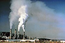 Before flue gas desulfurization was installed, the emissions from the
Four Corners Generating Station
in
New Mexico
contained a significant amount of sulfur dioxide.
Before flue gas desulfurization was installed, the emissions from the
Four Corners Generating Station
in
New Mexico
contained a significant amount of sulfur dioxide.
 The
G. G. Allen Steam Station
scrubber (North Carolina)
The
G. G. Allen Steam Station
scrubber (North Carolina)
Flue-gas desulfurization
(
FGD
) is a set of technologies used to remove
sulfur dioxide
(
SO
2
) from
exhaust flue gases of fossil-fuel power plants
, and from the emissions of other sulfur oxide emitting processes such as waste
incineration
, petroleum refineries, cement and lime kilns.
Methods
[
edit
]
Since stringent environmental regulations limiting
SO
2
emissions have been enacted in many countries,
SO
2
is being removed from flue gases by a variety of methods. Common methods used:
For a typical coal-fired power station, flue-gas desulfurization (FGD) may remove 90 per cent or more of the
SO
2
in the flue gases.
[2]
History
[
edit
]
Methods of removing
sulfur dioxide
from boiler and furnace exhaust gases have been studied for over 150 years. Early ideas for flue gas desulfurization were established in
England
around 1850.
With the construction of large-scale power plants in England in the 1920s, the problems associated with large volumes of
SO
2
from a single site began to concern the public. The
SO
2
emissions problem did not receive much attention until 1929, when the
House of Lords
upheld the claim of a landowner against the Barton Electricity Works of the
Manchester Corporation
for damages to his land resulting from
SO
2
emissions. Shortly thereafter, a press campaign was launched against the erection of power plants within the confines of London. This outcry led to the imposition of
SO
2
controls on all such power plants.
[3]
The first major FGD unit at a utility was installed in 1931 at
Battersea Power Station
, owned by
London Power Company
. In 1935, an FGD system similar to that installed at Battersea went into service at Swansea Power Station. The third major FGD system was installed in 1938 at
Fulham Power Station
. These three early large-scale FGD installations were suspended during
World War II
, because the characteristic white vapour plumes would have aided location finding by enemy aircraft.
[4]
The FGD plant at Battersea was recommissioned after the war and, together with FGD plant at the new
Bankside B power station
opposite the City of London, operated until the stations closed in 1983 and 1981 respectively.
[5]
Large-scale FGD units did not reappear at utilities until the 1970s, where most of the installations occurred in the
United States
and
Japan
.
[3]
In 1970, the
U.S. Congress
passed the
Clean Air Act of 1970
(CAA). The law authorized development of federal regulations in the United States covering emissions from both stationary (industrial) and mobile sources, which were subsequently published by the
U.S. Environmental Protection Agency
(EPA). In 1977, Congress amended the law to require more stringent controls on air emissions.
[6]
In response to the CAA requirements, the
American Society of Mechanical Engineers
(ASME) authorized the formation of the PTC 40 Standards Committee in 1978. This committee first convened in 1979 with the purpose of developing a standardized "procedure for conducting and reporting performance tests of FGD systems and reporting the results in terms of the following categories: (a) emissions reduction, (b) consumable and utilities, (c) waste and by-product characterization and amount."
[7]
The first code draft was approved by ASME in 1990 and adopted by the
American National Standards Institute
(ANSI) in 1991. The PTC 40-1991 Standard was available for public use for those units affected by the 1990 Clean Air Act Amendments. In 2006, the PTC 40 Committee reconvened following EPA publication of the Clean Air Interstate Rule (CAIR) in 2005.
[8]
In 2017, the revised PTC 40 Standard was published. This revised standard (PTC 40-2017) covers Dry and Regenerable FGD systems and provides a more detailed Uncertainty Analysis section. This standard is currently in use today by companies around the world.
As of June 1973, there were 42 FGD units in operation, 36 in Japan and 6 in the United States, ranging in capacity from 5
MW
to 250 MW.
[9]
As of around 1999 and 2000, FGD units were being used in 27 countries, and there were 678 FGD units operating at a total power plant capacity of about 229
gigawatts
. About 45% of the FGD capacity was in the U.S., 24% in
Germany
, 11% in Japan, and 20% in various other countries. Approximately 79% of the units, representing about 199 gigawatts of capacity, were using lime or limestone wet scrubbing. About 18% (or 25 gigawatts) utilized spray-dry scrubbers or sorbent injection systems.
[10]
[11]
[12]
FGD on ships
[
edit
]
The International Maritime Organization (
IMO
) has adopted guidelines on the approval, installation and use of exhaust gas scrubbers (exhaust gas cleaning systems) on board ships to ensure compliance with the sulphur regulation of
MARPOL Annex VI
.
[13]
Flag States must approve such systems and port States can (as part of their
port state control
) ensure that such systems are functioning correctly. If a scrubber system is not functioning properly (and the IMO procedures for such malfunctions are not adhered to), port States can sanction the ship. The
United Nations Convention on the Law Of the Sea
also bestows port States with a right to regulate (and even ban) the use of open loop scrubber systems within ports and internal waters.
[14]
Sulfuric acid mist formation
[
edit
]
Fossil fuels
such as coal and oil can contain a significant amount of sulfur. When
fossil fuels
are burned, about 95 percent or more of the sulfur is generally converted to
sulfur dioxide
(
SO
2
). Such conversion happens under normal conditions of temperature and of oxygen present in the
flue gas
. However, there are circumstances under which such reaction may not occur.
SO
2
can further oxidize into
sulfur trioxide
(
SO
3
) when excess oxygen is present and gas temperatures are sufficiently high. At about 800 °C, formation of
SO
3
is favored. Another way that
SO
3
can be formed is through catalysis by metals in the fuel. Such reaction is particularly true for heavy fuel oil, where a significant amount of
vanadium
is present. In whatever way
SO
3
is formed, it does not behave like
SO
2
in that it forms a liquid
aerosol
known as
sulfuric acid
(
H
2
SO
4
) mist that is very difficult to remove. Generally, about 1% of the sulfur dioxide will be converted to
SO
3
. Sulfuric acid mist is often the cause of the blue haze that often appears as the flue gas plume dissipates. Increasingly, this problem is being addressed by the use of wet
electrostatic precipitators
.
FGD chemistry
[
edit
]
Basic principles
[
edit
]
Most FGD systems employ two stages: one for
fly ash
removal and the other for
SO
2
removal. Attempts have been made to remove both the fly ash and
SO
2
in one scrubbing vessel. However, these systems experienced severe maintenance problems and low removal efficiency. In wet scrubbing systems, the flue gas normally passes first through a fly ash removal device, either an electrostatic precipitator or a baghouse, and then into the
SO
2
-absorber. However, in dry injection or spray drying operations, the
SO
2
is first reacted with the lime, and then the flue gas passes through a particulate control device.
Another important design consideration associated with wet FGD systems is that the flue gas exiting the absorber is saturated with water and still contains some
SO
2
. These gases are highly corrosive to any downstream equipment such as fans, ducts, and stacks. Two methods that may minimize corrosion are: (1) reheating the gases to above their
dew point
, or (2) using materials of construction and designs that allow equipment to withstand the corrosive conditions. Both alternatives are expensive. Engineers determine which method to use on a site-by-site basis.
Scrubbing with an alkali solid or solution
[
edit
]
 Schematic design of the absorber of an FGD
SO
2
is an
acid gas
, and, therefore, the typical sorbent slurries or other materials used to remove the
SO
2
from the flue gases are alkaline. The reaction taking place in wet scrubbing using a
CaCO
3
(
limestone
) slurry produces
calcium sulfite
(
CaSO
3
) and may be expressed in the simplified dry form as:
- CaCO
3
(s)
+
SO
2
(g)
→
CaSO
3
(s)
+
CO
2
(g)
When wet scrubbing with a
Ca(OH)
2
(
hydrated lime
) slurry, the reaction also produces
CaSO
3
(
calcium sulfite
) and may be expressed in the simplified dry form as:
- Ca(OH)
2
(s)
+
SO
2
(g)
→
CaSO
3
(s)
+
H
2
O
(l)
When wet scrubbing with a
Mg(OH)
2
(
magnesium hydroxide
) slurry, the reaction produces
MgSO
3
(
magnesium sulfite
) and may be expressed in the simplified dry form as:
- Mg(OH)
2
(s)
+
SO
2
(g)
→
MgSO
3
(s)
+
H
2
O
(l)
To partially offset the cost of the FGD installation, some designs, particularly dry sorbent injection systems, further oxidize the
CaSO
3
(calcium sulfite) to produce marketable
CaSO
4
·2H
2
O
(
gypsum
) that can be of high enough quality to use in
wallboard
and other products. The process by which this synthetic gypsum is created is also known as forced oxidation:
- 2
CaSO
3
(aq)
+ 4
H
2
O
(l)
+
O
2
(g)
→ 2 (
CaSO
4
·2H
2
O
(s)
)
A natural alkaline usable to absorb
SO
2
is seawater. The
SO
2
is absorbed in the water, and when oxygen is added reacts to form sulfate ions
SO
2?
4
and free
H
+
. The surplus of
H
+
is offset by the carbonates in seawater pushing the carbonate equilibrium to release
CO
2
gas:
- SO
2
(g)
+
H
2
O
(l)
+
1
/
2
O
2
(g)
→
SO
2?
4
(aq)
+ 2
H
+
- HCO
?
3
+
H
+
→
H
2
O
(l)
+
CO
2
(g)
In industry
caustic soda
(
NaOH
) is often used to scrub
SO
2
, producing
sodium sulfite
:
- 2
NaOH
(aq)
+
SO
2
(g)
→
Na
2
SO
3
(aq)
+
H
2
O
(l)
[15]
Types of wet scrubbers used in FGD
[
edit
]
To promote maximum
gas?liquid surface area
and residence time, a number of wet scrubber designs have been used, including spray towers, venturis, plate towers, and mobile
packed beds
. Because of scale buildup, plugging, or erosion, which affect FGD dependability and absorber efficiency, the trend is to use simple scrubbers such as spray towers instead of more complicated ones. The configuration of the tower may be vertical or horizontal, and flue gas can flow concurrently, countercurrently, or crosscurrently with respect to the liquid. The chief drawback of spray towers is that they require a higher liquid-to-gas ratio requirement for equivalent
SO
2
removal than other absorber designs.
FGD scrubbers produce a scaling wastewater that requires treatment to meet U.S. federal discharge regulations.
[16]
However, technological advancements in
ion-exchange membranes
and
electrodialysis
systems has enabled high-efficiency treatment of FGD wastewater to meet recent EPA discharge limits.
[17]
The treatment approach is similar for other highly scaling industrial wastewaters.
Venturi-rod scrubbers
[
edit
]
A
venturi scrubber
is a converging/diverging section of duct. The converging section accelerates the gas stream to high velocity. When the liquid stream is injected at the throat, which is the point of maximum velocity, the turbulence caused by the high gas velocity atomizes the liquid into small droplets, which creates the surface area necessary for mass transfer to take place. The higher the pressure drop in the venturi, the smaller the droplets and the higher the surface area. The penalty is in power consumption.
For simultaneous removal of
SO
2
and fly ash, venturi scrubbers can be used. In fact, many of the industrial sodium-based throwaway systems are venturi scrubbers originally designed to remove particulate matter. These units were slightly modified to inject a sodium-based scrubbing liquor. Although removal of both particles and
SO
2
in one vessel can be economic, the problems of high pressure drops and finding a scrubbing medium to remove heavy loadings of fly ash must be considered. However, in cases where the particle concentration is low, such as from oil-fired units, it can be more effective to remove particulate and
SO
2
simultaneously.
Packed bed scrubbers
[
edit
]
A packed scrubber consists of a tower with packing material inside. This packing material can be in the shape of saddles, rings, or some highly specialized shapes designed to maximize the contact area between the dirty gas and liquid. Packed towers typically operate at much lower pressure drops than venturi scrubbers and are therefore cheaper to operate. They also typically offer higher
SO
2
removal efficiency. The drawback is that they have a greater tendency to plug up if particles are present in excess in the exhaust air stream.
Spray towers
[
edit
]
A
spray tower
is the simplest type of scrubber. It consists of a tower with spray nozzles, which generate the droplets for surface contact.
Spray towers
are typically used when circulating a slurry (see below). The high speed of a venturi would cause erosion problems, while a packed tower would plug up if it tried to circulate a slurry.
Counter-current packed towers are infrequently used because they have a tendency to become plugged by collected particles or to scale when
lime
or
limestone
scrubbing slurries are used.
Scrubbing reagent
[
edit
]
As explained above, alkaline sorbents are used for scrubbing flue gases to remove
SO
2
. Depending on the application, the two most important are
lime
and
sodium hydroxide
(also known as
caustic soda
). Lime is typically used on large coal- or oil-fired boilers as found in power plants, as it is very much less expensive than caustic soda. The problem is that it results in a slurry being circulated through the scrubber instead of a solution. This makes it harder on the equipment. A spray tower is typically used for this application. The use of lime results in a slurry of calcium sulfite (
CaSO
3
) that must be disposed of. Fortunately, calcium sulfite can be oxidized to produce by-product gypsum (
CaSO
4
·2H
2
O
) which is marketable for use in the building products industry.
Caustic soda is limited to smaller combustion units because it is more expensive than lime, but it has the advantage that it forms a solution rather than a slurry. This makes it easier to operate. It produces a "
spent caustic
" solution of
sodium sulfite
/bisulfite (depending on the pH), or sodium sulfate that must be disposed of. This is not a problem in a
kraft pulp
mill for example, where this can be a source of makeup chemicals to the recovery cycle.
Scrubbing with sodium sulfite solution
[
edit
]
It is possible to scrub
sulfur dioxide
by using a cold solution of
sodium sulfite
; this forms a sodium hydrogen sulfite solution. By heating this solution it is possible to reverse the reaction to form sulfur dioxide and the sodium sulfite solution. Since the sodium sulfite solution is not consumed, it is called a regenerative treatment. The application of this reaction is also known as the
Wellman?Lord process
.
In some ways this can be thought of as being similar to the reversible
liquid?liquid extraction
of an
inert gas
such as
xenon
or
radon
(or some other solute which does not undergo a chemical change during the extraction) from water to another phase. While a chemical change does occur during the extraction of the sulfur dioxide from the gas mixture, it is the case that the extraction equilibrium is shifted by changing the temperature rather than by the use of a chemical reagent.
Gas-phase oxidation followed by reaction with ammonia
[
edit
]
A new, emerging flue gas desulfurization technology has been described by the
IAEA
.
[18]
It is a
radiation
technology where an intense beam of
electrons
is fired into the flue gas at the same time as
ammonia
is added to the gas. The Chendu power plant in China started up such a flue gas desulfurization unit on a 100 MW scale in 1998. The Pomorzany power plant in Poland also started up a similar sized unit in 2003 and that plant removes both sulfur and nitrogen oxides. Both plants are reported to be operating successfully.
[19]
[20]
However, the accelerator design principles and manufacturing quality need further improvement for continuous operation in industrial conditions.
[21]
No
radioactivity
is required or created in the process. The electron beam is generated by a device similar to the
electron gun
in a TV set. This device is called an accelerator. This is an example of a radiation chemistry process
[20]
where the physical effects of radiation are used to process a substance.
The action of the electron beam is to promote the oxidation of sulfur dioxide to sulfur(VI) compounds. The ammonia reacts with the sulfur compounds thus formed to produce
ammonium sulfate
, which can be used as a nitrogenous
fertilizer
. In addition, it can be used to lower the nitrogen oxide content of the flue gas. This method has attained industrial plant scale.
[19]
[22]
Facts and statistics
[
edit
]
- The information in this section was obtained from a US EPA published fact sheet.
[23]
Flue gas desulfurization scrubbers have been applied to combustion units firing coal and oil that range in size from 5 MW to 1,500 MW.
Scottish Power
are spending £400 million installing FGD at
Longannet power station
, which has a capacity of over 2,000 GW. Dry scrubbers and spray scrubbers have generally been applied to units smaller than 300 MW.
FGD has been fitted by
RWE npower
at
Aberthaw Power Station
in south Wales using the seawater process and works successfully on the 1,580 MW plant.
Approximately 85% of the flue gas desulfurization units installed in the US are wet scrubbers, 12% are spray dry systems, and 3% are dry injection systems.
The highest
SO
2
removal efficiencies (greater than 90%) are achieved by wet scrubbers and the lowest (less than 80%) by dry scrubbers. However, the newer designs for dry scrubbers are capable of achieving efficiencies in the order of 90%.
In spray drying and dry injection systems, the flue gas must first be cooled to about 10?20 °C above
adiabatic
saturation
to avoid wet solids deposition on downstream equipment and plugging of baghouses.
The capital, operating and maintenance costs per
short ton
of
SO
2
removed (in 2001 US dollars) are:
- For wet scrubbers larger than 400 MW, the cost is $200 to $500 per ton
- For wet scrubbers smaller than 400 MW, the cost is $500 to $5,000 per ton
- For spray dry scrubbers larger than 200 MW, the cost is $150 to $300 per ton
- For spray dry scrubbers smaller than 200 MW, the cost is $500 to $4,000 per ton
Alternative methods of reducing sulfur dioxide emissions
[
edit
]
An alternative to removing
sulfur
from the flue gases after burning is to remove the sulfur from the fuel before or during combustion.
Hydrodesulfurization
of fuel has been used for treating
fuel oils
before use.
Fluidized bed combustion
adds lime to the fuel during combustion. The lime reacts with the
SO
2
to form
sulfates
which become part of the
ash
.
This elemental sulfur is then separated and finally recovered at the end of the process for further usage in, for example, agricultural products. Safety is one of the greatest benefits of this method, as the whole process takes place at
atmospheric pressure
and ambient temperature. This method has been developed by Paqell, a joint venture between
Shell Global Solutions
and Paques.
[24]
See also
[
edit
]
References
[
edit
]
- ^
"Dry Sorbent Injection Technology | Nox Control Systems"
.
- ^
Compositech Products Manufacturing Inc.
"Flue Gas Desulfurization ? FGD Wastewater Treatment | Compositech Filters Manufacturer"
.
www.compositech-filters.com
. Retrieved
30 March
2018
.
- ^
a
b
Biondo, S.J.; Marten, J.C. (October 1977). "A History of Flue Gas Desulphurization Systems Since 1850".
Journal of the Air Pollution Control Association
.
27
(10): 948?61.
doi
:
10.1080/00022470.1977.10470518
.
- ^
Sheail, John (1991).
Power in Trust: The environmental history of the Central Electricity Generating Board
. Oxford: Clarendon Press. p. 52.
ISBN
0-19-854673-4
.
- ^
Murray, Stephen (2019). "The politics and economics of technology: Bankside power station and the environment, 1945-81".
The London Journal
.
44
(2): 113?32.
doi
:
10.1080/03058034.2019.1583454
.
S2CID
159395306
.
- ^
"Evolution of the Clean Air Act"
. Washington, D.C.: U.S. Environmental Protection Agency (EPA). 3 January 2017.
- ^
ASME, 2017, "Flue Gas Desulfurization Units", ASME PTC 40-2017
- ^
"Clean Air Interstate Rule"
. EPA. 2016.
- ^
Beychok, Milton R.,
Coping With SO
2
, Chemical Engineering/Deskbook Issue, 21 October 1974
- ^
Nolan, Paul S.,
Flue Gas Desulfurization Technologies for Coal-Fired Power Plants
, The Babcock & Wilcox Company, U.S., presented by Michael X. Jiang at the Coal-Tech 2000 International Conference, November 2000, Jakarta, Indonesia
- ^
Rubin, Edward S.; Yeh, Sonia; Hounshell, David A.; Taylor, Margaret R. (2004).
"Experience curves for power plant emission control technologies"
.
International Journal of Energy Technology and Policy
.
2
(1?2): 52?69.
doi
:
10.1504/IJETP.2004.004587
.
S2CID
28265636
. Archived from
the original
on 9 October 2014.
- ^
Beychok, Milton R.,
Comparative economics of advanced regenerable flue gas desulfurization processes
, EPRI CS-1381, Electric Power Research Institute, March 1980
- ^
"Index of MEPC Resolutions and Guidelines related to MARPOL Annex VI"
. Archived from
the original
on 18 November 2015.
- ^
Jesper Jarl Fanø (2019). Enforcing
International Maritime Legislation on Air Pollution through UNCLOS
. Hart Publishing.
- ^
Prasad, D.S.N.; et al. (April?June 2010).
"Removal of Sulphur Dioxide from Flue Gases in Thermal Plants"
(PDF)
.
Rasayan J. Chem
.
3
(2). Jaipur, India: 328?334.
ISSN
0976-0083
.
- ^
"Steam Electric Power Generating Effluent Guidelines ? 2015 Final Rule"
. EPA. 30 November 2018.
- ^
"Lowering Cost and Waste in Flue Gas Desulfurization Wastewater Treatment"
.
Power Mag
. Electric Power. March 2017
. Retrieved
6 April
2017
.
- ^
IAEA Factsheet
about pilot plant in Poland.
- ^
a
b
Haifeng, Wu.
"Electron beam application in gas waste treatment in China"
(PDF)
.
Proceedings of the FNCA 2002 workshop on application of electron accelerator
. Beijing, China: INET Tsinghua University.
- ^
a
b
Section of IAEA 2003 Annual Report
Archived
21 February 2007 at the
Wayback Machine
- ^
Chmielewski, Andrzej G. (2005).
"Application of ionizing radiation to environment protection"
(PDF)
.
Nukleonika
.
50
(Suppl. 3). Warsaw, Poland: Institute of Nuclear Chemistry and Technology: S17?S24.
ISSN
0029-5922
.
- ^
Industrial Plant for Flue Gas Treatment with High Power Electron Accelerator
by A.G. Chmielewski, Warsaw University of Technology, Poland.
- ^
"Air Pollution Control Technology Fact Sheet: Flue Gas Desulfurization"
(PDF)
.
Clean Air Technology Center
. EPA. 2003. EPA 452/F-03-034.
- ^
"HIOPAQ Oil & Gas Process Description"
. Utrecht, The Netherlands: Paqell BV
. Retrieved
10 June
2019
.
External links
[
edit
]