Method for converting signals between digital and analog
"Sigma delta" redirects here. For the sorority, see
Sigma Delta
.
 Figure 1: Full process of a 1
st
-order synchronous ΔΣ
ADC
(top) and ΔΣ
DAC
(bottom). Each contains a ΔΣ modulation
negative feedback loop
(the curly bracket) which outputs a new
ΔΣM
result on each clock cycle, which is fed back for computing the next
ΔΣM
result. The full conversion process for each typically includes post-
filtering
for demodulation and pre-filtering to remove
aliases
and noise. Analog is green. Digital is blue. The DDC (Digital-to-Digital Converter) requantizes its input from a high-bitdepth to a low-bitdepth.
Figure 1: Full process of a 1
st
-order synchronous ΔΣ
ADC
(top) and ΔΣ
DAC
(bottom). Each contains a ΔΣ modulation
negative feedback loop
(the curly bracket) which outputs a new
ΔΣM
result on each clock cycle, which is fed back for computing the next
ΔΣM
result. The full conversion process for each typically includes post-
filtering
for demodulation and pre-filtering to remove
aliases
and noise. Analog is green. Digital is blue. The DDC (Digital-to-Digital Converter) requantizes its input from a high-bitdepth to a low-bitdepth.
 1-bit synchronous ΔΣ modulation (blue) of a sine wave (red).
Delta-sigma
(
ΔΣ
; or
sigma-delta
,
ΣΔ
) modulation is an
oversampling
method for encoding
signals
into low
bit depth
digital signals
at a very high
sample-frequency
as part of the process of delta-sigma
analog-to-digital converters
(ADCs) and
digital-to-analog converters
(DACs). Delta-sigma modulation achieves high
quality
by utilizing a
negative feedback
loop during quantization to the lower bit depth that continuously corrects
quantization errors
and moves
quantization noise
to higher frequencies well above the original signal's
bandwidth
. Subsequent
low-pass filtering
for
demodulation
easily removes this high frequency noise and
time averages
to achieve high accuracy in amplitude which can be ultimately encoded as
pulse-code modulation
(PCM).
Both ADCs and DACs can employ delta-sigma modulation. A delta-sigma ADC (e.g. Figure 1 top) encodes an
analog signal
using high-frequency delta-sigma modulation and then applies a
digital filter
to demodulate it to a high-bit digital output at a lower sampling-frequency. A delta-sigma DAC (e.g. Figure 1 bottom) encodes a high-resolution digital input signal into a lower-resolution but higher sample-frequency signal that may then be mapped to
voltages
and smoothed with an analog filter for demodulation. In both cases, the temporary use of a low bit depth signal at a higher sampling frequency simplifies circuit design and takes advantage of the efficiency and high accuracy in time of
digital electronics
.
Primarily because of its cost efficiency and reduced circuit complexity, this technique has found increasing use in modern electronic components such as DACs, ADCs,
frequency synthesizers
,
switched-mode power supplies
and
motor controllers
.
[1]
The coarsely-quantized output of a delta-sigma ADC is occasionally used directly in signal processing or as a representation for signal storage (e.g.,
Super Audio CD
stores the raw output of a 1-bit delta-sigma modulator).
While this article focuses on
synchronous
modulation, which requires a precise clock for quantization,
asynchronous
delta-sigma modulation instead runs without a clock.
Motivation
[
edit
]
When transmitting an analog signal directly, all
noise
in the system and transmission is added to the analog signal, reducing its quality.
Digitizing
it enables noise-free transmission, storage, and processing. There are many methods of digitization.
In Nyquist-rate ADCs, an analog signal is
sampled
at a relatively low sampling frequency just above its
Nyquist rate
(twice the signal's highest frequency) and
quantized
by a multi-level quantizer to produce a multi-bit
digital signal
. Such higher-bit methods seek accuracy in amplitude directly, but require extremely precise components and so may suffer from poor linearity.
Advantages of oversampling
[
edit
]
Oversampling converters instead produce a lower-bitdepth result at a much higher sampling frequency. This can achieve comparable quality by taking advantage of:
- Higher accuracy in time (afforded by high-speed digital circuits and highly accurate
clocks
).
- Higher linearity afforded by low-bit ADCs and DACs (for instance, a 1-bit DAC that only outputs two values of a precise high voltage and a precise low voltage is perfectly linear, in principle).
- Noise shaping
: moving noise to higher frequencies above the signal of interest, so they can be easily removed with
low-pass filtering
.
- Reduced steepness requirement for the analog low-pass
anti-aliasing filters
. High-order filters with a flat passband cost more to make in the analog domain than in the digital domain.
Frequency/resolution tradeoff
[
edit
]
Another key aspect given by oversampling is the frequency/resolution tradeoff. The decimation filter put after the modulator not only filters the whole sampled signal in the band of interest (cutting the noise at higher frequencies), but also reduces the sampling rate, and hence the representable frequency range, of the signal, while increasing the sample amplitude resolution. This improvement in amplitude resolution is obtained by a sort of
averaging
of the higher-data-rate bitstream.
Improvement over delta modulation
[
edit
]
Delta modulation
is an earlier related low-bit oversampling method that also uses
negative feedback
, but only encodes the
derivative
of the signal (its
delta
) rather than its
amplitude
. The result is a stream of
marks and spaces
representing up or down of the signal's movement, which must be
integrated
to reconstruct the signal's amplitude. Delta modulation has several drawbacks. The differentiation alters the signal's spectrum by amplifying high-frequency noise, attenuating low-frequencies,
[2]
and dropping the
DC
component. This makes its dynamic range and SNR inversely proportional to signal frequency. Delta modulation suffers from
slope overload
if signals move too fast. And it is susceptible to transmission disturbances that result in
cumulative error
.
Delta-sigma modulation rearranges the
integrator
and quantizer of a delta modulator, so that the output carries information corresponding to the amplitude of the input signal instead of just its derivative.
[3]
This also has the benefit of incorporating desirable
noise shaping
into the conversion process, to deliberately move
quantization noise
to frequencies higher than the signal. Since the accumulated error signal is lowpass filtered by the delta-sigma modulator's integrator before being quantized, the subsequent negative feedback of its quantized result effectively subtracts the low frequency components of the quantization noise while leaving the higher frequency components of the noise.
1-bit delta-sigma modulation is pulse-density modulation
[
edit
]
In the specific case of a single-bit synchronous ΔΣ ADC, an analog voltage signal is effectively converted into a pulse frequency, or pulse density, which can be understood as
pulse-density modulation
(PDM). A sequence of positive and negative pulses, representing bits at a known fixed rate, is very easy to generate, transmit, and accurately regenerate at the receiver, given only that the timing and sign of the pulses can be recovered. Given such a sequence of pulses from a delta-sigma modulator, the original waveform can be reconstructed with adequate precision.
The use of PDM as a signal representation is an alternative to PCM. Alternatively, the high frequency PDM can later be
downsampled
through a processed called
decimation
and requantized to convert it into a multi-bit PCM code at lower sampling frequency closer to the
Nyquist rate
of the frequency band of interest.
History and variations
[
edit
]
The seminal
[4]
paper combining feedback with oversampling to achieve
delta modulation
was by F. de Jager of
Philips Research Laboratories
in 1952.
[5]
 "Feedback Integrating System" by Charles B Brahm: The entire top half of its Fig 1 is a delta-sigma modulator. Box #10 is a two-input
integrator
. The 4-bit analog-to-digital quantizer uses designations "S" (sign), "1", "2", and "4" for each bit. Each "F" stands for
flip-flop
and each "G" is a gate, controlled by the 110 kHz oscillator.
"Feedback Integrating System" by Charles B Brahm: The entire top half of its Fig 1 is a delta-sigma modulator. Box #10 is a two-input
integrator
. The 4-bit analog-to-digital quantizer uses designations "S" (sign), "1", "2", and "4" for each bit. Each "F" stands for
flip-flop
and each "G" is a gate, controlled by the 110 kHz oscillator.
The principle of improving the resolution of a coarse quantizer by use of feedback, which is the basic principle of delta-sigma conversion, was first described in a 1954-filed patent by
C. Chapin Cutler
of
Bell Labs
.
[6]
It was not named as such until a 1962 paper
[7]
by Inose et al. of
University of Tokyo
, which came up with the idea of adding a filter in the forward path of the delta modulator.
[8]
[note 1]
However, Charles B Brahm of
United Aircraft Corp
[9]
in 1961 filed a patent "Feedback integrating system"
[10]
with a feedback loop containing an integrator with multi-bit quantization shown in its Fig 1.
[2]
Wooley's "The Evolution of Oversampling Analog-to-Digital Converters"
[4]
gives more history and references to relevant patents. Some avenues of variation (which may be applied in different combinations) are the modulator's order, the quantizer's bitdepth, the manner of
decimation
, and the oversampling ratio.
Higher-order modulator
[
edit
]
 Figure 2: Noise-feedback 2
nd
-order ΔΣ modulator ADC.
Figure 2: Noise-feedback 2
nd
-order ΔΣ modulator ADC.
Noise of the quantizer can be further shaped by replacing the quantizer itself with another ΔΣ modulator. This creates a 2
nd
-order modulator, which can be rearranged in a cascaded fashion (Figure 2).
[2]
This process can be repeated to increase the order even more.
While 1
st
-order modulators are unconditionally stable, stability analysis must be performed for higher-order noise-feedback modulators. Alternatively, noise-feedforward configurations are always stable and have simpler analysis.
[11]
§6.1
Multi-bit quantizer
[
edit
]
The modulator can also be classified by the bit depth of its quantizer. A quantizer that distinguishes between
N-levels
is called a
log
2
N
bit quantizer. For example, a simple comparator has 2 levels and so is 1 bit quantizer; a 3-level quantizer is called a "1.5" bit quantizer; a 4-level quantizer is a 2-bit quantizer; a 5-level quantizer is called a
2.5-bit
quantizer.
[12]
Higher bit quantizers inherently produce less quantization noise.
One criticism of 1-bit quantization is that adequate amounts of
dither
cannot be used in the feedback loop, so distortion can be heard under some conditions (more discussion at
Direct Stream Digital § DSD vs. PCM
).
[13]
[14]
Subsequent decimation
[
edit
]
Decimation is strongly associated with delta-sigma modulation, but is distinct and outside the scope of this article. The original 1962 paper didn't describe decimation. Oversampled data in the early days was sent as is. The proposal to
decimate
oversampled delta-sigma data using
digital filtering
before converting it into
PCM
audio was made by D. J. Goodman at Bell Labs in 1969,
[15]
to reduce the ΔΣ signal from its high sampling rate while increasing its
bit depth
. Decimation may be done in a separate chip on the receiving end of the delta-sigma bit stream, sometimes by a dedicated module inside of a
microcontroller
,
[16]
which is useful for interfacing with PDM
MEMS microphones
,
[17]
though many ΔΣ ADC
integrated circuits
include decimation. Some microcontrollers even incorporate both the modulator and decimator.
[18]
Decimation filters most commonly used for ΔΣ ADCs, in order of increasing complexity and quality, are:
- Boxcar moving average filter
(
simple moving average
or
sinc-in-frequency
or sinc
1
filter): This is the easiest digital filter and retains a sharp step response, but is mediocre at separating frequency bands
[19]
and suffers from
intermodulation distortion
. The filter can be implemented by simply counting how many samples during a larger sampling interval are high. The 1974 paper from another Bell Labs researcher, J. C. Candy, "A Use of Limit Cycle Oscillations to Obtain Robust Analog-to-Digital Converters"
[20]
was one of the early examples of this.
- Cascaded integrator?comb filters
: These are called sinc
N
filters, equivalent to cascading the above sinc
1
filter N times and rearranging the order of operations for computational efficiency. Lower N filters are simpler, settle faster, and have less attenuation in the baseband, while higher N filters are slightly more complex and settle slower and have more droop in the passband, but better attenuate undesired high frequency noise. Compensation filters can however be applied to counteract undesired passband attenuation.
[21]
Sinc
N
filters are appropriate for decimating sigma delta modulation down to four times the Nyquist rate.
[22]
The height of the first sideload is -13·N dB and the height of successive lobes fall off gradually, but only the areas around the nulls will alias into the low frequency band of interest; for instance when downsampling by 8, the largest
aliased
high frequency component may be -16 dB below the peak of the band of interest with a sinc
1
filter but -40 dB below for a sinc
3
filter, and if only interested in a narrower bandwidth, even fewer high frequency components will alias into it (see Figures 7?9 of Lyons article).
[23]
- Windowed
sinc-in-time (brick-wall in frequency) filters
: Although the
sinc function
's
infinite support
prevents it from being
realizable in finite time
, the sinc function can instead be
windowed
to realize
finite impulse response
filters. This approximated filter design, while maintaining
almost no
attenuation of the lower-frequency band of interest, still removes
almost all
undesired high-frequency noise. The downside is poor performance in the time domain (e.g.
step response
overshoot and ripple), higher delay (i.e. their
convolution
time is inversely proportional to their cutoff transition steepness), and higher computational requirements.
[24]
They are the
de facto standard
for
high fidelity
digital audio converters.
Reduction of baseband noise by increasing oversampling ratio and ΔΣM order
[
edit
]
 Figure 3: Top: a sine wave input overlaid with its synchronous ΔΣ representation made using a high oversampling ratio. Middle: filtering the ΔΣ representation produces an approximation of the original sine wave. Bottom: residual error of the ΔΣ ADC, with and without adding
dither
noise.
Figure 3: Top: a sine wave input overlaid with its synchronous ΔΣ representation made using a high oversampling ratio. Middle: filtering the ΔΣ representation produces an approximation of the original sine wave. Bottom: residual error of the ΔΣ ADC, with and without adding
dither
noise.
When a signal is quantized, the resulting signal can be approximated by addition of
white noise
with approximately equal intensity across the entire spectrum. In reality, the quantization noise is, of course, not independent of the signal and this dependence results in
limit cycles
and is the source of idle tones and pattern noise in delta-sigma converters. However, adding
dithering
noise (Figure 3) reduces such
distortion
by making quantization noise more random.
ΔΣ ADCs reduce the amount of this noise in the
baseband
by spreading it out and shaping it so it is mostly in higher frequencies. It can then be easily filtered out with inexpensive digital filters, without high-precision analog circuits needed by Nyquist ADCs.
Oversampling to spread out quantization noise
[
edit
]
Quantization noise in the baseband frequency range (from
DC
to
 ) may be reduced by increasing the oversampling ratio (OSR) defined by

where
 is the sampling frequency and
is the
Nyquist rate
(the minimum sampling rate needed to avoid aliasing, which is twice the original signal's maximum frequency
is the sampling frequency and
is the
Nyquist rate
(the minimum sampling rate needed to avoid aliasing, which is twice the original signal's maximum frequency
 ). Since oversampling is typically done in powers of two,
 represents how many times OSR is doubled.
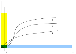 Figure 4: Noise shaping curves and noise spectrum in 1
st
, 2
nd
, and 3
rd
-order ΔΣ modulators.
Figure 4: Noise shaping curves and noise spectrum in 1
st
, 2
nd
, and 3
rd
-order ΔΣ modulators.
As illustrated in Figure 4, the total amount of quantization noise is the same both in a Nyquist converter (yellow + green areas) and in an oversampling converter (blue + green areas). But oversampling converters distribute that noise over a much wider frequency range. The benefit is that the total amount of noise in the frequency band of interest is dramatically smaller for oversampling converters (just the small green area), than for a Nyquist converter (yellow + green total area).
Noise shaping
[
edit
]
Figure 4 shows how ΔΣ modulation
shapes noise
to further reduce the amount of quantization noise in the baseband in exchange for increasing noise at higher frequencies (where it can be easily filtered out). The curves of higher-order ΔΣ modulators achieve even greater reduction of noise in the baseband.
These curves are derived using mathematical tools called the
Laplace transform
(for
continuous-time signals
, e.g. in an ADC's modulation loop) or the
Z-transform
(for
discrete-time signals
, e.g. in a DAC's modulation loop). These transforms are useful for converting harder math from the
time domain
into simpler math in the
complex
frequency domain
of the
complex variable
 (in the Laplace domain) or
 (in the z-domain).
Analysis of ΔΣ ADC modulation loop in Laplace domain
[
edit
]
Figure 5 represents the 1
st
-order ΔΣ ADC modulation loop (from Figure 1) as a continuous-time
linear time-invariant system
in the Laplace domain with the equation:
 Figure 5: ΔΣ modulation loop in Laplace domain. Integration is multiplication by
 and quantization is approximated by adding noise.
![{\displaystyle [{\text{in}}({\text{s}})-\Delta \Sigma {\text{M}}({\text{s}})]\cdot {\frac {1}{\text{s}}}+{\text{noise}}({\text{s}})=\Delta \Sigma {\text{M}}({\text{s}})\,.}](https://wikimedia.org/api/rest_v1/media/math/render/svg/9b9d083b4beb5197f302afdd3c097978e21f69c3)
The
Laplace transform of integration
of a function of time corresponds to simply multiplication by
in Laplace notation. The integrator is assumed to be an ideal integrator to keep the math simple, but a
real integrator
(or similar filter) may have a more complicated expression.
The process of quantization is approximated as addition with a quantization error noise source. The noise is often assumed to be white and independent of the signal, though as
quantization (signal processing) § Additive noise model
explains that is not always a valid assumption (particularly for low-bit quantization).
Since the system and Laplace transform are linear, the total behavior of this system can be analyzed by separating how it affects the input from how it affects the noise:
[11]
§6

Low-pass filter on input
[
edit
]
To understand how the system affect the input signal only, the noise is temporarily imagined to be 0:
![{\displaystyle [{\text{in}}({\text{s}})-\Delta \Sigma {\text{M}}_{\text{in}}({\text{s}})]\cdot {\frac {1}{\text{s}}}+0=\Delta \Sigma {\text{M}}_{\text{in}}({\text{s}})\,,}](https://wikimedia.org/api/rest_v1/media/math/render/svg/5a8a3f0da21116ae108305caffc662a419507043)
which can be rearranged to yield the following
transfer function
:

This transfer function has a single
pole
at
 in the
complex plane
, so it effectively acts as a 1
st
-order low-pass filter on the input signal. (Note: its
cutoff frequency
could be adjusted as desired by including multiplication by a constant in the loop).
in the
complex plane
, so it effectively acts as a 1
st
-order low-pass filter on the input signal. (Note: its
cutoff frequency
could be adjusted as desired by including multiplication by a constant in the loop).
High-pass filter on noise
[
edit
]
To understand how the system affects the noise only, the input instead is temporarily imagined to be 0:
![{\displaystyle [0-\Delta \Sigma {\text{M}}_{\text{noise}}({\text{s}})]\cdot {\frac {1}{\text{s}}}+{\text{noise}}({\text{s}})=\Delta \Sigma {\text{M}}_{\text{noise}}({\text{s}})\,,}](https://wikimedia.org/api/rest_v1/media/math/render/svg/fab09aca140acee35f265ed5aad3d0747d4cc8c9)
which can be rearranged to yield the following transfer function:

This transfer function has a single zero at
 and a single pole at
 so the system effectively acts as a high-pass filter on the noise that starts at 0 at
DC
, then gradually rises until it reaches the cutoff frequency, and then levels off.
so the system effectively acts as a high-pass filter on the noise that starts at 0 at
DC
, then gradually rises until it reaches the cutoff frequency, and then levels off.
Analysis of synchronous ΔΣ modulation loop in z-domain
[
edit
]
The synchronous ΔΣ DAC's modulation loop (Figure 6) meanwhile is in discrete-time and so its analysis is in the z-domain. It is very similar to the above analysis in Laplace domain and produces similar curves. Note: many sources
[11]
§6.1
[25]
[26]
also analyze a ΔΣ ADC's modulation loop in the z-domain, which implicitly treats the continuous analog input as a discrete-time signal. This may be a valid approximation provided that the input signal is already bandlimited and can be assumed to be not changing on time scales higher than the sampling rate. It is particularly appropriate when the modulator is implemented as a
switched capacitor
circuit, which work by transferring charge between capacitors in clocked time steps.
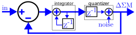 Figure 6: ΔΣ modulation loop in the z-domain.
Integration in discrete-time can be an
accumulator
which repeatedly sums its input
![{\displaystyle x[n]}](https://wikimedia.org/api/rest_v1/media/math/render/svg/864cbbefbdcb55af4d9390911de1bf70167c4a3d) with the previous result of its summation
with the previous result of its summation
![{\displaystyle y[n]=x[n]+y[n-1].}](https://wikimedia.org/api/rest_v1/media/math/render/svg/55affaa374d6e3008554b05d99462c1ceca20121) This is represented in the z-domain by feeding back a summing node's output
This is represented in the z-domain by feeding back a summing node's output
 though a 1-clock cycle delay stage (notated as
 ) into another input of the summing node, yielding
 .
Its transfer function
.
Its transfer function
 is often used to label integrators in block diagrams.
In a ΔΣ DAC, the quantizer may be called a
requantizer
or a
digital-to-digital converter
(DDC), because its input is already digital and quantized but is simply reducing from a higher bitdepth to a lower bitdepth digital signal. This is represented in the z-domain by another
delay stage in series with adding quantization noise. (Note: some sources may have swapped ordering of the
and additive noise stages.)
The modulator's z-domain equation arranged like Figure 6 is:
![{\displaystyle [{\text{in}}({\text{z}})-\Delta \Sigma {\text{M}}({\text{z}})]\cdot {\frac {1}{1-{\text{z}}^{\text{-1}}}}\cdot {\text{z}}^{\text{-1}}+{\text{noise}}({\text{z}})=\Delta \Sigma {\text{M}}({\text{z}})\,,}](https://wikimedia.org/api/rest_v1/media/math/render/svg/07279ce729a4b3aebd704f68517e470ea68094c6)
which can be rearranged to express the output in terms of the input and noise:

The input simply comes out of the system delayed by one clock cycle. The noise term's multiplication by

represents a
first difference backward
filter (which has a single pole at the origin and a single zero at

) and thus high-pass filters the noise.
Higher order modulators
[
edit
]
Without getting into the mathematical details,
[25]
(equations 8-11)
cascading
 integrators to create an
 -order
modulator results in:
-order
modulator results in:

Since this
first difference backwards
filter is now raised to the power
it will have a more steeper noise shaping curve, for improved properties of greater attenuation in the baseband, so a dramatically larger portion of the noise is above the baseband and can be easily filtered by an ideal low-pass filter.
Theoretical effective number of bits
[
edit
]
The theoretical
signal-to-noise ratio
(SNR) in
decibels
(dB) for a sinusoid input travelling through a
-order
modulator with a
 OSR (and followed by an ideal low-pass decimation filter) can be mathematically derived to be approximately:
[25]
(equations 12-21)
OSR (and followed by an ideal low-pass decimation filter) can be mathematically derived to be approximately:
[25]
(equations 12-21)

The theoretical
effective number of bits
(ENOB) resolution is thus improved by

bits when doubling the OSR (incrementing
), and by

bits when incrementing the order. For comparison, oversampling a Nyquist ADC (without any noise shaping) only improves its ENOB by

bits for every doubling of the OSR,
[27]
which is only
1
⁄
3
of the ENOB growth rate of a 1
st
-order ΔΣM.
Theoretical SNR & ENOB versus ΔΣM order & oversampling ratio (OSR)
|
|
Oversampling ratio
|
each OSR
doubling
|
| 2
4
OSR
|
2
5
OSR
|
2
6
OSR
|
2
7
OSR
|
2
8
OSR
|
1
st
-order:
|
24 dB
3
+
3
⁄
4
bits
|
33 dB
5
+
1
⁄
4
bits
|
42 dB
6
+
3
⁄
4
bits
|
51 dB
8
+
1
⁄
4
bits
|
60 dB
9
+
3
⁄
4
bits
|
+
1
+
1
⁄
2
bits
|
2
nd
-order:
|
39 dB
6
+
1
⁄
4
bits
|
54 dB
8
+
3
⁄
4
bits
|
69 dB
11
+
1
⁄
4
bits
|
84 dB
13
+
3
⁄
4
bits
|
99 dB
16
+
1
⁄
4
bits
|
+
2
+
1
⁄
2
bits
|
3
rd
-order:
|
53 dB
8
+
3
⁄
4
bits
|
75 dB
12
+
1
⁄
4
bits
|
96 dB
15
+
3
⁄
4
bits
|
117 dB
19
+
1
⁄
4
bits
|
138 dB
22
+
3
⁄
4
bits
|
+
3
+
1
⁄
2
bits
|
4
th
-order:
|
68 dB
11
+
1
⁄
4
bits
|
95 dB
15
+
3
⁄
4
bits
|
112 dB
20
+
1
⁄
4
bits
|
149 dB
24
+
3
⁄
4
bits
|
177 dB
29
+
1
⁄
2
bits
|
+
4
+
1
⁄
2
bits
|
5
th
-order:
|
83 dB
13
+
1
⁄
2
bits
|
116 dB
19 bits
|
149 dB
24
+
1
⁄
2
bits
|
182 dB
30 bits
|
215 dB
35
+
1
⁄
2
bits
|
+
5
+
1
⁄
2
bits
|
6
th
-order:
|
99 dB
16 bits
|
137 dB
22
+
1
⁄
2
bits
|
176 dB
29 bits
|
215 dB
35
+
1
⁄
2
bits
|
254 dB
42 bits
|
+
6
+
1
⁄
2
bits
|
each additional order:
|
+
2
+
1
⁄
2
bits
|
+
3
+
1
⁄
2
bits
|
+
4
+
1
⁄
2
bits
|
+
5
+
1
⁄
2
bits
|
+
6
+
1
⁄
2
bits
|
|
These datapoints are theoretical. In practice, circuits inevitably experience other noise sources that limit resolution, making the higher-resolution cells impractical.
Relationship to delta modulation
[
edit
]
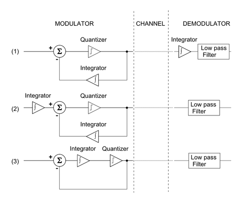 Figure 7: Derivation of delta-sigma from delta modulation
Delta-sigma modulation is related to
delta modulation
by the following steps (Figure 7):
[11]
§6
- Start with a block diagram of a delta modulator/demodulator.
- The
linearity property of integration
,
 , makes it possible to move the integrator, which reconstructs the analog signal in the demodulator section, in front of the delta modulator.
- Again, the linearity property of integration allows the two integrators to be combined and a delta-sigma modulator/demodulator block diagram is obtained.
If
quantization
were
homogeneous
(e.g., if it were
linear
), the above would be a sufficient derivation of their hypothetical equivalence. But because the quantizer is
not
homogeneous, delta-sigma is
inspired
by delta modulation, but the two are distinct in operation.
From the first block diagram in Figure 7, the integrator in the feedback path can be removed if the feedback is taken directly from the input of the low-pass filter. Hence, for delta modulation of input signal
v
in
, the low-pass filter sees the signal

However, delta-sigma modulation of the same input signal places at the low-pass filter

In other words, doing delta-sigma modulation instead of delta modulation has effectively swapped the ordering of the integrator and quantizer operations. The net effect is a simpler implementation that has the profound added benefit of shaping the quantization noise to be mostly in frequencies above the signals of interest. This effect becomes more dramatic with increased
oversampling
, which allows for quantization noise to be somewhat programmable. On the other hand, delta modulation shapes both noise and signal equally.
Additionally, the quantizer (e.g.,
comparator
) used in delta modulation has a small output representing a small step up and down the quantized approximation of the input while the quantizer used in delta-sigma must take values
outside
of the range of the input signal.
In general, delta-sigma has some advantages versus delta modulation:
- The structure is simplified as
- only one integrator is needed,
- the demodulator can be a simple linear filter (e.g., RC or LC filter) to reconstruct the signal, and
- the quantizer (e.g., comparator) can have full-scale outputs.
- The quantized value is the integral of the difference signal, which
- makes it less sensitive to the rate of change of the signal, and
- helps capture low frequency and DC components.
Analog-to-digital conversion example
[
edit
]
Figure 8a: Schematic of simple delta-sigma converter.
Figure 8b: Simulated scope view of key voltage signals over time. Each minor vertical division is 1 μs, which corresponds to a sampling event of the 1 MHz clock.
Delta-sigma ADCs vary in complexity. The below circuit focuses on a simple 1st-order, 2-level quantization synchronous delta-sigma ADC without decimation.
Simplified circuit example
[
edit
]
To ease understanding, a simple
circuit schematic
(Figure 8a) using ideal elements is
simulated
(Figure 8b voltages). It is functionally the same Analog-to-Digital ΔΣ modulation loop in Figure 1 (note: the 2-input inverting integrator combines the summing junction and integrator and produces a negative feedback result, and the flip-flop combines the sampled quantizer and conveniently naturally functions as a 1-bit DAC too).
The 20 kHz input
sine wave
s(t)
is converted to a 1-bit
PDM
digital result
Q(t)
. 20 kHz is used as an example because that is considered the upper
limit of human hearing
.
This circuit can be laid out on a
breadboard
with inexpensive discrete components (note some variations use different biasing and use simpler
RC low-pass filters
for integration instead of
op amps
).
[28]
[29]
For simplicity, the
D flip-flop
is powered by dual supply voltages of V
DD
= +1 V and V
SS
= -1 V, so its binary output
Q(t)
is either +1 V or -1 V.
2-input inverting integrator
[
edit
]
The 2-input inverting
op amp integrator
combines
s(t)
with
Q(t)
to produce
?(t)
:

The Greek letter
epsilon
is used because
?(t)
contains the accumulated
error
that is repeatedly corrected by the feedback mechanism. While both its inputs
s(t)
and
Q(t)
vary between -1 and 1 volts,
?(t)
instead only varies by a couple
millivolts
about 0 V.
Because of the integrator's
negative
sign, when
?(t)
next gets sampled to produce
Q(t)
, the +
Q(t)
in this integral actually represents
negative
feedback from the previous clock cycle.
Quantizer and sampler flip-flop
[
edit
]
An ideal
D flip-flop
samples
?(t)
at the clock rate of 1
MHz
. The scope view (Figure 8b) has a minor division equal to the
sampling period
of 1 μs, so every minor division corresponds to a sampling event. Since the flip-flop is assumed to be ideal, it treats any input voltage greater than 0 V as logical high and any input voltage smaller than 0 V as logical low, no matter how close it is to 0 V (ignoring issues of sample-and-hold time violations and
metastability
).
Whenever a sampling event occurs:
- if
?(t)
is above the 0 V threshold, then
Q(t)
will go high (+1 V), or
- if
?(t)
is below the 0 V threshold, then
Q(t)
will go low (-1 V).
Q(t)
is sent out as the resulting PDM output and also fed back to the 2-input inverting integrator.
Demodulation
[
edit
]
The rightmost integrator performs digital-to-analog conversion on
Q(t)
to produce a demodulated analog output
r(t)
, which reconstructs the original sine wave input as piece-wise linear diagonal segments. Although
r(t)
appears coarse at this 50x oversampling rate,
r(t)
can be low-pass filtered to isolate the original signal. As the sampling rate is increased relative to the input signal's maximum frequency,
r(t)
will more closely approximate the original input
s(t)
.
Digital-to-analog conversion
[
edit
]
It is worth noting that if no decimation ever took place, the digital representation from a 1-bit delta-sigma modulator is simply a
PDM signal, which can easily be converted to analog
using a
low-pass filter
, as simple as a
resistor and capacitor
.
[29]
However, in general, a delta-sigma DAC converts a
discrete time series
signal of
digital samples
at a high-bitdepth into a low-bitdepth (often 1-bit) signal, usually at a much higher sampling rate. That delta-modulated signal can then be accurately converted into analog (since lower bitdepth DACs are easier to be highly-linear), which then goes through inexpensive low-pass filtering in the analog domain to remove the high-frequency quantization noise inherent to the delta-sigma modulation process.
Upsampling
[
edit
]
As the
discrete Fourier transform
and
discrete-time Fourier transform
articles explain, a periodically-sampled signal inherently contains multiple higher frequency copies or "images" of the signal. It is often desirable to remove these higher-frequency images prior to the performing the actual delta-sigma modulation stage, in order to ease requirements on the eventual analog low-pass filter. This can be done by
upsampling using an interpolation filter
and is often the first step prior to performing delta-sigma modulation in DACs. Upsampling is strongly associated with delta-sigma DACs but not strictly part of the actual delta-sigma modulation stage (similar to how decimation is strongly associated with delta-sigma ADCs but not strictly part of delta-sigma modulation either), and the details are out of the scope of this article.
Digital-to-digital delta-sigma modulation
[
edit
]
The modulation loop in Figure 6 in
§ Noise shaping
can easily be laid out with basic digital elements of a subtractor for the difference, an
accumulator
for the integrator, and a lower-bit
register
for the quantization, which carries over the most-significant bit(s) from the integrator to be the feedback for the next cycle.
Multi-stage noise shaping
[
edit
]
This simple 1
st
-order modulation can be improved by cascading two or more overflowing accumulators, each of which is equivalent to a 1
st
-order delta-sigma modulator. The resulting multi-stage noise shaping (MASH)
[30]
structure has a steeper
noise shaping
property, so is commonly used in digital audio. The carry outputs are combined through summations and delays to produce a binary output, the width of which depends on the number of stages (order) of the MASH. Besides its noise shaping function, it has two more attractive properties:
- simple to implement in hardware; only common digital blocks such as
accumulators
,
adders
, and
D flip-flops
are required
- unconditionally stable (there are no feedback loops outside the accumulators)
Naming
[
edit
]
The technique was first presented in the early 1960s by professor Yasuhiko Yasuda while he was a student at
the University of Tokyo
.
[31]
[11]
The name
delta-sigma
comes directly from the presence of a delta modulator and an integrator, as firstly introduced by Inose et al. in their patent
[
clarification needed
]
application.
[7]
That is, the name comes from integrating or
summing
differences
, which, in mathematics, are operations usually associated with Greek letters
sigma
and
delta
respectively.
In the 1970s,
Bell Labs
engineers used the terms "sigma-delta" because the precedent was to name variations on delta modulation with adjectives preceding "delta", and an
Analog Devices
magazine editor justified in 1990 that the functional hierarchy is "sigma-delta", because it computes the integral of a difference.
[32]
Both names
sigma-delta
and
delta-sigma
are frequently used.
Asynchronous delta-sigma modulation
[
edit
]
 Figure 9: 1-bit asynchronous ΔΣ modulation produces a PWM output (blue in bottom plot) which is subtracted from the input signal (green in top plot) to form an error signal (blue in top plot). This error is integrated (magenta in middle plot). When the integral of the error exceeds the limits (the upper and lower grey lines in middle plot), the PWM output changes state.
Kirkkert and Miller published a continuous-time variant called "Asynchronous Delta Sigma Modulation" (ADSM or ASDM) in 1975 which uses either a
Schmitt trigger
(i.e. a comparator with
hysteresis
) or (as the paper argues is equivalent) a comparator with fixed delay.
[33]
In the example in Figure 9, when the integral of the error exceeds its limits, the output changes state, producing a
pulse-width modulated
(PWM) output wave.
Amplitude information is converted, without quantization noise, into time information of the output PWM.
[34]
To convert this continuous time PWM to discrete time, the PWM may be sampled by a time-to-digital converter, whose limited resolution adds noise which can be shaped by feeding it back.
[35]
See also
[
edit
]
Notes
[
edit
]
- ^
The delta-sigma configuration as described by Inose et al. in 1962 was devised to solve problems in the accurate transmission of analog signals. In that application it was the pulse stream that was transmitted and the original analog signal recovered with a lowpass filter after the received pulses had been reformed. This low pass filter performed the summation function associated with Σ. The highly mathematical treatment of transmission errors was introduced by them and is appropriate when applied to the pulse stream but these errors are lost in the accumulation process associated with Σ.
References
[
edit
]
- ^
Sangil Park,
Principles of Sigma-Delta Modulation for Analog-to-Digital Converters
(PDF)
, Motorola
, retrieved
2017-09-01
- ^
a
b
c
Razavi, Behzad (2016-06-21).
"A Circuit for all Seasons: The Delta-Sigma Modulator"
(PDF)
.
IEEE Solid-State Circuits Magazine
.
8
(2): 10?15.
doi
:
10.1109/MSSC.2016.2543061
.
Archived
(PDF)
from the original on 2024-02-09
. Retrieved
2024-03-16
.
- ^
Inose, H.; Yasuda, Y. (1963-11-01).
"A unity bit coding method by negative feedback"
.
Proceedings of the IEEE
.
51
(11): 1524?1535.
doi
:
10.1109/PROC.1963.2622
.
ISSN
1558-2256
– via
IEEE Xplore
.
- ^
a
b
Wooley, Bruce A. (2012-03-22).
"The Evolution of Oversampling Analog-to-Digital Converters"
(PDF)
.
IEEE
.
Archived
(PDF)
from the original on 2023-06-28
. Retrieved
2023-06-28
.
- ^
F. de Jager, "Delta modulation, a method of PCM transmission using the 1-unit code," Philips Res. Rep., vol. 7, pp. 442?466, 1952.
- ^
US patent 2967962
, Cutler, Cassius C., "Transmission systems employing quantization", issued March 8, 1960
- ^
a
b
Inose, H.; Yasuda, Y.; Murakami, J. (1962-05-06).
"A Telemetering System by Code Modulation - Δ- ΣModulation"
.
IRE Transactions on Space Electronics and Telemetry
. SET-8 (3) (published 1962-09-01): 204?209.
doi
:
10.1109/IRET-SET.1962.5008839
.
ISSN
2331-1657
.
S2CID
51647729
– via
IEEE Xplore
.
- ^
"Continuous-time sigma-delta modulation"
.
Continuous-Time Sigma-Delta Modulation for A/D Conversion in Radio Receivers: Chapter 4: Continuous-time sigma-delta modulation
.
Springer Publishing
. 2001. pp. 29?71.
doi
:
10.1007/0-306-48004-2_3
.
ISBN
9780306480041
.
Archived
from the original on 2023-06-29
. Retrieved
2023-06-28
.
- ^
"Charles Brahm Obituary (1926 - 2021) - Hartford, CT - Hartford Courant"
.
Legacy.com
. Retrieved
2024-03-16
.
- ^
US3192371A
, Brahm, Charles B., "Feedback integrating system", issued 1965-06-29
- ^
a
b
c
d
e
Sangil Park,
Principles of sigma-delta modulation for analog-to-digital converters
(PDF)
, Motorola, archived from
the original
(PDF)
on 2006-06-21
- ^
a
b
Sigma-delta class-D amplifier and control method for a sigma-delta class-D amplifier
by Jwin-Yen Guo and Teng-Hung Chang
- ^
Lipschitz, Stanley P.; Vanderkooy, John (2000-09-22).
"Why Professional 1-Bit Sigma-Delta Conversion is a Bad Idea"
(PDF)
. Archived from
the original
(PDF)
on 2022-11-02.
- ^
Lipshitz, Stanley P.; Vanderkooy, John (2001-05-12).
"Why 1-Bit Sigma-Delta Conversion is Unsuitable for High-Quality Applications"
(PDF)
.
Archived
(PDF)
from the original on 2023-04-30
. Retrieved
2023-08-28
.
- ^
"Data Converter Architectures: Chapter 3"
(PDF)
. Retrieved
October 27,
2018
.
- ^
"AN4990: Getting started with sigma-delta digital interface on applicable STM32 microcontrollers"
(PDF)
.
STMicroelectronics
. March 2018.
Archived
(PDF)
from the original on 2022-01-20
. Retrieved
2023-09-03
.
- ^
Kite, Thomas (2012).
"Understanding PDM Digital Audio"
(PDF)
.
Archived
(PDF)
from the original on 2023-06-30
. Retrieved
2023-08-24
.
- ^
"MSP430i2xx Family"
(PDF)
.
Texas Instruments
. 2014.
Archived
(PDF)
from the original on 2022-10-15
. Retrieved
2023-09-03
.
- ^
Smith, Steven W. (1999).
"Chapter 15: Moving Average Filters"
(PDF)
.
The Scientist and Engineer's Guide to Digital Signal Processing
(2nd ed.). San Diego, Calif: California Technical Pub.
ISBN
978-0-9660176-4-9
.
- ^
Candy, J. (1974).
"A Use of Limit Cycle Oscillations to Obtain Robust Analog-to-Digital Converters"
.
IEEE Transactions on Communications
.
22
(3): 298?305.
doi
:
10.1109/TCOM.1974.1092194
.
ISSN
1558-0857
.
- ^
"AN-455: Understanding CIC Compensation Filters"
(PDF)
.
Altera
. 2007.
Archived
(PDF)
from the original on 2023-04-05
. Retrieved
2024-01-03
.
- ^
Candy, J.C. (1986).
"Decimation for Sigma Delta Modulation"
.
IEEE Transactions on Communications
.
34
: 72?76.
doi
:
10.1109/TCOM.1986.1096432
. Retrieved
2024-01-03
.
- ^
Lyons, Rick (2020-03-26).
"A Beginner's Guide To Cascaded Integrator-Comb (CIC) Filters"
.
dsprelated.com
.
Archived
from the original on 2023-10-22
. Retrieved
2024-01-03
.
- ^
Smith, Steven W. (1999).
"Chapter 16: Windowed-Sinc Filters"
(PDF)
.
The Scientist & Engineer's Guide to Digital Signal Processing
(2nd ed.). San Diego, Calif: California Technical Pub.
ISBN
978-0-9660176-4-9
.
- ^
a
b
c
Van Ess, Dave.
"Signals From Noise: Calculating Delta-Sigma SNRs"
(PDF)
.
Archived
(PDF)
from the original on 2023-08-06
. Retrieved
2023-08-22
.
- ^
Reiss, Joshua D. (2008).
"UNDERSTANDING SIGMA?DELTA MODULATION: The Solved and Unsolved Issues"
(PDF)
. J. Audio Eng. Soc., Vol. 56, No. 1/2, 2008 January/February.
Archived
(PDF)
from the original on 2023-09-01
. Retrieved
2023-09-01
.
- ^
Brown, Ryan; Singh, Sameer (2016).
"Application Report: General Oversampling of MSP ADCs for Higher Resolution"
(PDF)
.
Texas Instruments
.
Archived
(PDF)
from the original on 2022-09-01
. Retrieved
2023-09-01
.
- ^
"Activity: Delta - Sigma Modulator [Analog Devices Wiki]"
.
Analog Devices
. 2021-01-09.
Archived
from the original on 2023-04-01
. Retrieved
2023-07-01
.
- ^
a
b
Ellsworth, Jeri
(2012-11-05).
"One Bit ADC - Short Circuits"
.
YouTube
. Retrieved
2023-06-29
.
- ^
"15-25 MHZ Fractional-N Synthesizer"
.
- ^
"?見と?明のデジタル博物館卓越?究デ?タベ?ス?電??情報通信?連??究情報(登?番?671)"
. Archived from
the original
on 2022-04-08.
- ^
Sheingold, Dan (1990).
"Editor's Notes: Σ-? or ?-Σ?"
(PDF)
.
Analog Devices
.
Archived
(PDF)
from the original on 2023-06-29
. Retrieved
2023-06-28
.
- ^
Kikkert, C. J.; Miller, D. J. (1975-04-01).
"Asynchronous Delta Sigma Modulation"
.
Proceedings of the IREE Australia
.
36
(4): 83?88.
- ^
Stork, Milan (2015).
"Asynchronous sigma-delta modulator and fast demodulator"
.
2015 25th International Conference Radioelektronika (RADIOELEKTRONIKA)
: 180?183.
doi
:
10.1109/RADIOELEK.2015.7129003
.
ISBN
978-1-4799-8117-5
.
- ^
Wei, Chen (2014).
"Asynchronous Sigma Delta Modulators for Data Conversion - Ph.D. Thesis"
(PDF)
.
Imperial College of London
. p. 88.
Archived
(PDF)
from the original on 2020-07-10
. Retrieved
2024-03-16
.
Further reading
[
edit
]
External links
[
edit
]